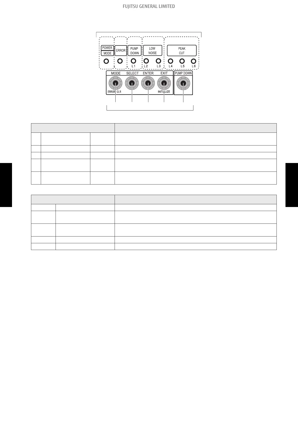
¢ Switch buttons and the functions
SW1
S
W2
SW3 SW4 SW5
(1) (2) (3) (4) (5)
LED lamps
Switch buttons
LED lamp Function or operation method
(1) POWER/MODE Green
Lights on while power on.
Local setting in outdoor unit or error code is displayed with blink.
(2) ERROR Red Blinks during error operation.
(3) PUMP DOWN (L1) Orange Lights on during pump down operation.
(4)
LOW NOISE MODE
(L2 and L3)
Orange
Lights on during “Low noise mode” when local setting is activated.
(Lighting pattern of L2 and L3 indicates low noise level.)
(5)
PEAK CUT MODE
(L4, L5, and L6)
Orange
Lights on during “Peak cut mode” when local setting is activated.
(Lighting pattern of L4, L5, and L6 indicates peak cut level.)
Switch button Function or operation method
SW1 MODE Switches between “Local setting” and “Error code display”.
SW2 SELECT
Switches between the individual “Local settings” and the “Error code
displays”.
SW3 ENTER
Switches between the individual “Local settings” and the “Error code
displays”.
SW4 EXIT Returns to “Operation status display”.
SW5 PUMP DOWN Starts the pump down operation.
2-1. Local setting switch buttons - (05-11) - 2. Function settings (For outdoor unit: AOTG34KMTC only)
FIELD
WORKING
FIELD
WORKING
 Loading...