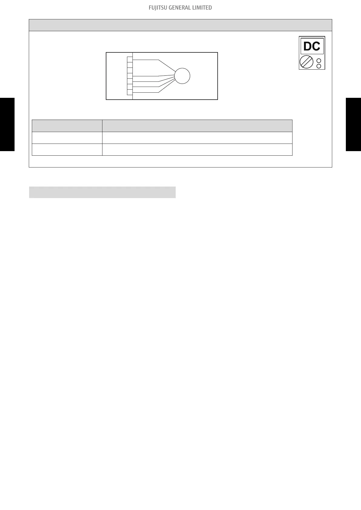
Check point 4. Check output voltage of main PCB
Check outdoor unit circuit diagram and the voltage. (Measure at main PCB side con-
nector)
1
2
3
4
5
6
7
BL
ACK
WHITE
YELLOW
RED
FM
FAN MOTOR
BROWN
NOTE: For details of wiring diagram, refer to "Wiring diagrams" in Chapter 2.
TECHNICAL DATA AND PARTS LIST on page 02-15.
Read wire DC voltage
Red—Black 200—400 V
White—Black 15 ±1.5V
-> If the voltage is not correct, replace Main PCB.
↓
End
2-32. E: 97. Outdoor unit fan motor error (Outdoor unit) - (03-47) - 2. Troubleshooting with error code
TROUBLESHOOTING
TROUBLESHOOTING
 Loading...