13-6. Wired remote controller (UTY-RLRY)
¢
Overview
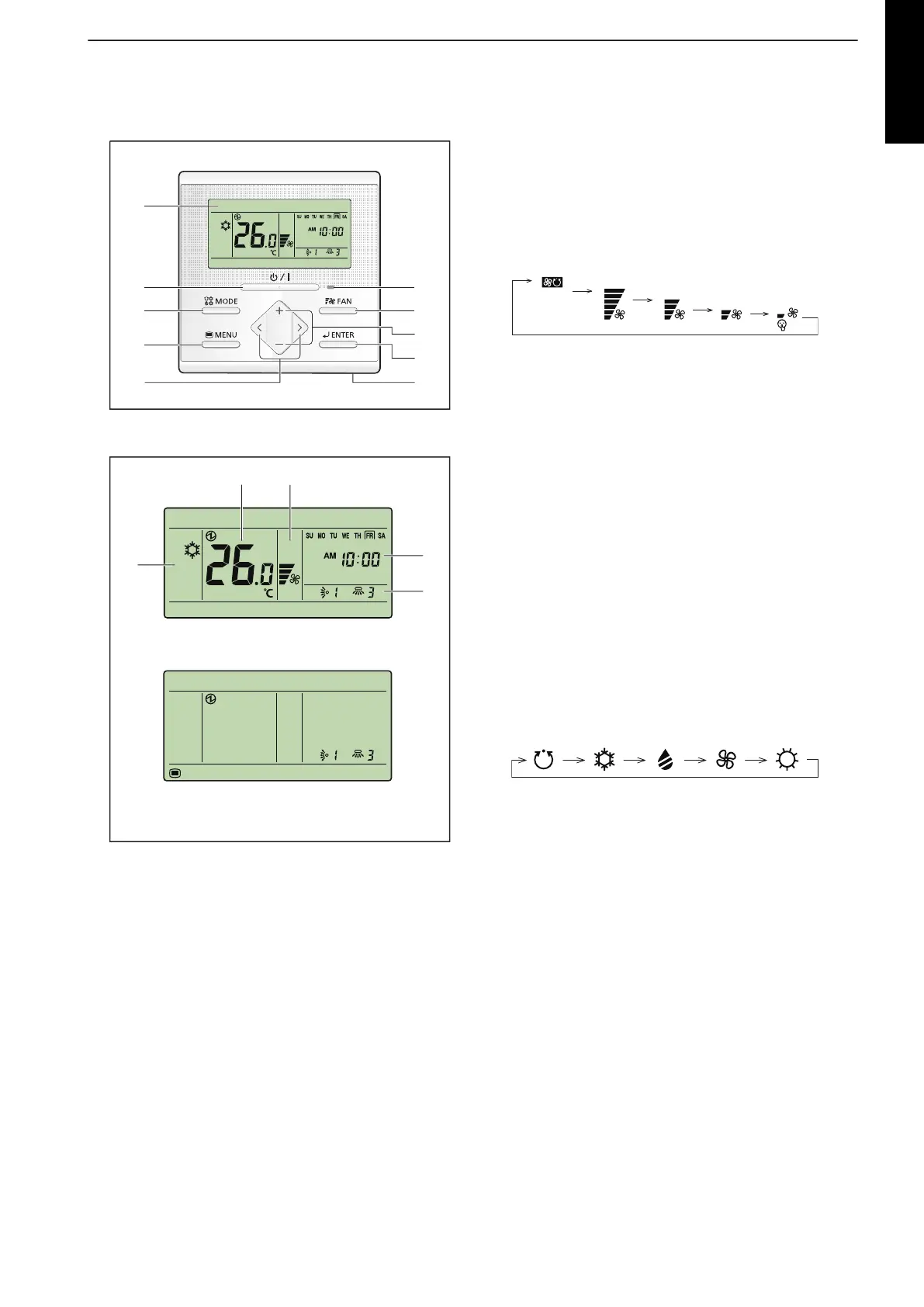
Display panel
o
m
n
lk
Monitor mode screen
(Example: Airflow direction setting)
Setting screen
a LED lamp (Operation indicator)
Lights while the indoor unit is operating. Blinks when an
error occurred.
b FAN button
Each time the button is pressed, fan speed switches as
follows:
c +, - buttons (Set temperature buttons)
Used to adjust temperature in Monitor mode screen.
+ button: Raise
- button: Lower
In Setting screen, used to select the setting items.
NOTE: When the operation mode is set to FAN, the tem-
perature cannot be adjusted.
d ENTER button
Used to enter setting items and settings.
e Room temperature sensor (inside)
Senses ambient temperature of unit.
f <, > buttons
Used to select setting items during the setting item se-
lection screen is displayed.
g MENU button
Used to display the setting item selection screen.
h MODE button
Each time the button is pressed, operation mode switch-
es as follows:
i On/Off button
Starts or stops the operation.
NOTE: On/Off button cannot be operated at screens oth-
er than the Monitor mode screen.
j Display panel
Displays Monitor mode screen or Setting screen.
Monitor mode screen is home screen of this controller,
and the basic operation is performed in this screen.
In Setting screen, several settings are adjustable.
k Temperature indicator
l Fan speed indicator
m Clock indicator
n Airflow direction indicator
o Operation mode indicator
NOTE:
For individual icons in Setting screen
and related functions, refer to the oper-
ation manual.
- 175 -
MULTI TYPE
5, 6 ROOMS TYPE
 Loading...