4-2. External output
→ith using external output function, some status signals are transmitted to the control PCB, and the
related LED lamp indicates the status of this product.
¢
Error status output
Signal on air conditioner error status is generated when a malfunction occurs.
• Circuit diagram example
Outdoor unit
control PCB
Example:
Relay unit
Connected unit (Locally purchased)
Example: Fan
Signal
Connector
1
2
1
2
12 V
On/
Off
P590
On/
Off
PA590
10m*
(33ft)
• Output voltage (Vcc): DC 12
V 50 mA or less
• *: Make the distance from
the PCB to the connected
unit within 33 ft (10 m).
Error
Normal
On
Off
Error status
Output signal
• Optional part
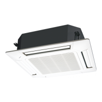
Part name Model name Exterior
External Connect Kit UT↔-↓→Z↓Z3
External output wire
4-2. External output - (05-47) - 4. External input and output (for 24-36 outdoor units)
FIELD
WORKING
FIELD
WORKING

 Loading...


