En-11
■
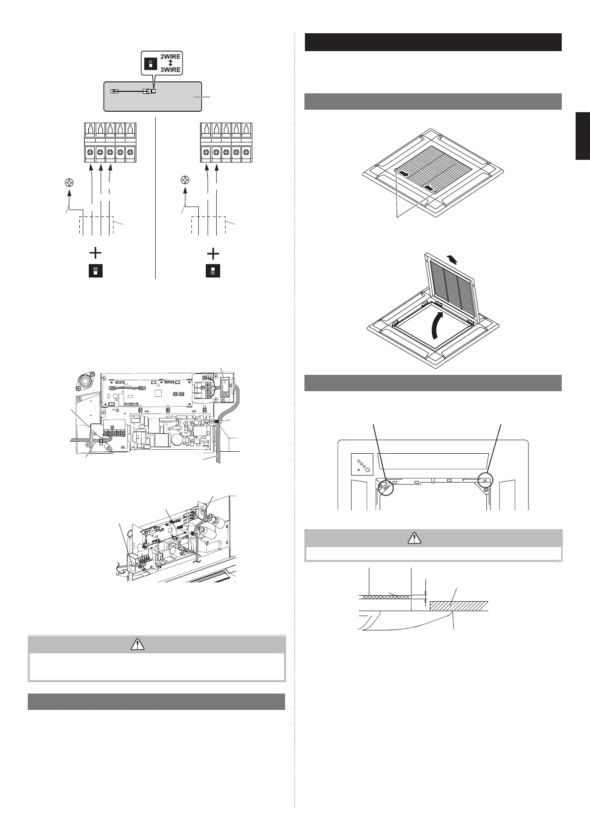
Remote controller cable
Y1 Y2
TO REMOTE CONTROL UNIT Ex IN
Y3 1 2 Y1 Y2
TO REMOTE CONTROL UNIT Ex IN
Y3 1 2
DIP switch
Print circuit board
(PCB)
2-wire type
White
Red
Remote
controller
cable
Remote controller
Factory setting “2 WIRE”
3-wire type
Black
White
Red
Remote
controller
cable
Remote controller
Set to “3 WIRE”
EarthEarth
Connecting the
Optional parts
*Earth (Ground) the remote controller if it has a earth (ground) wire.
NOTES: Be sure to change the DIP SW to the corresponding remote controller.
When a 2-wire remote controller is connected to a “3WIRE” setting, power will
not be supplied.
When a 3-wire remote controller is connected to a “2WIRE” setting, a
communication error will be detected.
(3) After wiring is complete, secure the remote controller cable, connection cable with
the cable clamps.
Connection cable
(power supply)
Cable tie
(accessories)
Wire clamper
(accessories)
Remote controller cable
Cable clamp
Remote controller cable
Wire clamper
(accessories)
Connection cable
(power supply)
Do not bind the connection cable (power supply) and other cables together.
(4) Seal the cable outlet or other gaps with putty to prevent dew condensation or insect
from entering the electric control box.
(5) Replace the control box cover.
CAUTION
Do not bundle the remote controller cable, or wire the remote controller cable in paral-
lel, with the indoor unit connection wire (to the outdoor unit) and the power supply
cable. It may cause erroneous operation.
3.7. Remote controller setting
To install and set the remote controller, refer to the installation manual of the remote
controller.
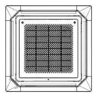
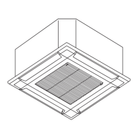
4. CASSETTE GRILLE INSTALLATION
• Installation according to the Installation instruction sheet Cassette grille.
• Be sure to confi rm there is no gap between the panel and main unit after installing the
Cassette grille.
4.1. Remove the intake grille
(1) Slide the 2 grille hooks.
Grille hook
(2) Open the intake grille and remove.
4.2. Installing the panel to indoor unit
(1) Install the cassette grille on the indoor unit.
“DRAIN” mark
“PIPE” mark
• Align the stamped marks on the cassette grille to the pipe and the drain of the indoor unit.
CAUTION
Use only the supplied screws to install the cassette grille.
Indoor unit
Sealant
Ceiling
5 ~ 7
Cassette grille
No gap between ceiling
and cassette grille
around entire perimeter
9379124119-03_IM.indb 119379124119-03_IM.indb 11 2019/2/22 16:51:382019/2/22 16:51:38
 Loading...