En-13
5.2.2. External output
• A twisted pair cable (22AWG) should be used. Maximum length of cable is 25 m (82 ft.).
• Use an external input and output cable with appropriate external dimension, depending
on the number of cables to be installed.
• Output voltage: Hi DC12V±2V, Lo 0V.
• Permissible current: 50mA
■
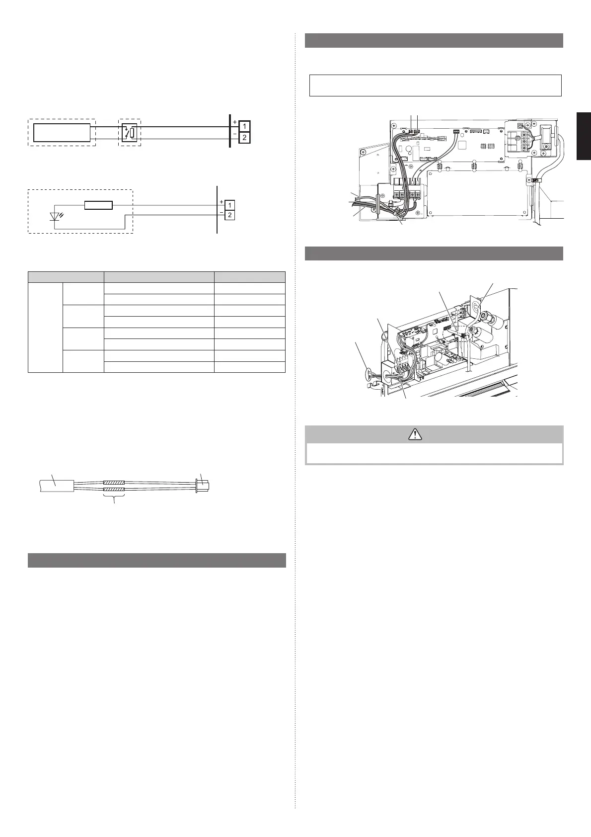
Output select
When interlocking with external device
CN47
PCB
Connected
device
Relay (locally purchased)
or
When displaying “Operation/Stop”
CN47
PCB
Connected device
Resistor
LED
■
Operation behavior
*If function setting “60” is set to “00”
Function setting Status Output voltage
60
00
Stop 0V
Operation DC 12 V
09
Normal 0V
Error DC 12 V
10
Indoor unit fan stop 0V
Indoor unit fan operation DC 12 V
11
External heater OFF 0 V
External heater ON DC 12V
5.2.3. Connection methods
■
Wire modifi cation
• Remove insulation from wire attached to wire kit connector.
• Remove insulation from locally purchased cable. Use crimp type insulated butt
connector to join fi eld cable and wire kit wire.
• Connect the wire with connecting wire with solder.
IMPORTANT:
Be sure to insulate the connection between the wires.
Locally purchased
Option parts
External output wire
Solder and insulate the connected parts.
• Connecting wires to the terminals.
Use ring terminals with insulating sleeves to connect to the terminal block.
• Connection terminals and wiring arrangement (Refer to “5.4. Other optional parts”)
5.3. Remote sensor (Optional parts)
5.3.1. Connection method
• Remove the existing connector and replace it with the remote sensor connector (ensure
that the correct connector is used).
• The original connector should be insulated to ensure that it does not come into contact
with other electrical circuitry.
• Connection terminals and wiring arrangement. (Refer to “5.4. Other optional parts”)
5.3.2. Setting for room temperature correction
When a remote sensor is connected, set the function setting of indoor unit as indicated
below.
• Function Number “30”:
Set the Setting Number to “00”. (Default)
• Function Number “31”:
Set the Setting Number to “02”.
* Refer to “7. FUNCTION SETTING” for details about Function number and Setting
value
5.4. Other optional parts
5.4.1. Connection method
• Connection terminals and wiring arrangement
In following fi gure, all the possible connections are done for description.
In actual installation, connections will differ according to each installation requirements.
External input
External input
and output PCB
Cable tie (accessories)
External output or
Fresh air intake
CN47CN65
5.5. Optional parts cable binding
Wire clamper (accessories)
Connection cable
(power supply)
Remote controller cable
Cable tie (accessories)
To various
optional kits
• Do not bind the connection cable (power supply) and other cables together.
CAUTION
To protect the cable insulation after opening a knockout hole, remove any burrs from
the edge of the hole.
9379124119-03_IM.indb 139379124119-03_IM.indb 13 2019/2/22 16:51:382019/2/22 16:51:38
 Loading...