En-15
■
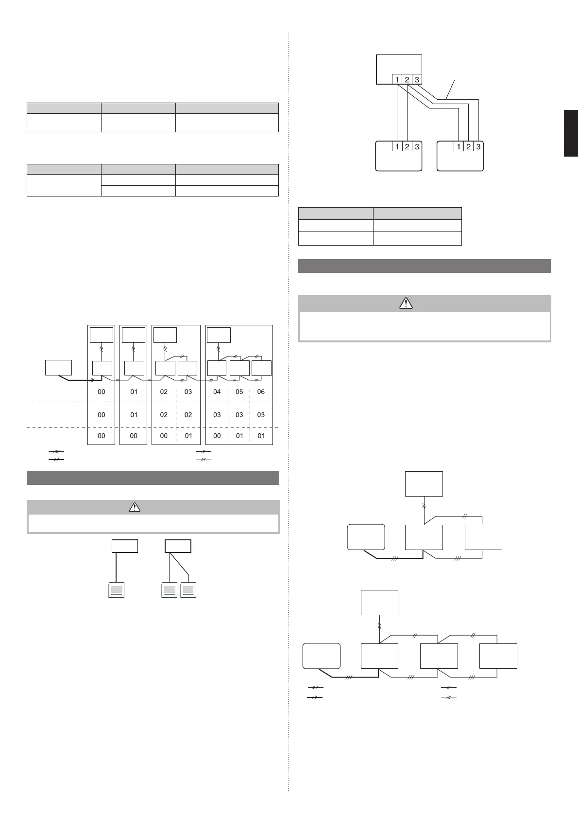
Settings when simultaneous Multi is included
(3) Remote controller setting
1. Turn on all of the indoor units.
* Turn on the indoor unit with the R.C. address “00” last.
(Within 1 minute)
2. Set the refrigerant circuit address.
Assign the same number to all of the indoor units connected to an outdoor unit.
(The unit is factory-set to “00”)
Function number Setting value Setting description
02 00 to 15
Refrigerant circuit address
00 to 15
3. Set the “Primary” and “Secondary” settings.
(Set the indoor unit that is connected to the outdoor unit using a connection cable
as the “Primary”.)
Function number Setting value Setting description
51
00 Primary
01 Secondary
4. After completing the function settings, turn off all of the indoor units, and then turn
them back on.
* If error code 21, 22, 24, or 27 is displayed, there may be an incorrect
setting. Perform the remote controller setting again.
NOTES:
• When different indoor unit models are connected using the group control system, some
functions may no longer be available.
• If the group control system contains multiple units that are operated simultaneously, con-
nect and set the units as shown below.
• Auto-changeover operates under the same mode with model R.C. address “00”.
• It should not be connected to any other Gr that is not of the same series (A**G only).
R.C. address
Standard
pair
Standard
pair
Simultaneous
twin
Simultaneous
triple
Refrigerant circuit
address setting
Primary/Secondary setting
(DIP switch setting)
(Function number 02)
(Function number 51)
Remote
controller
: Transmission cable, Power supply cable
: Power supply cable
: Connection cable
: Remote controller cable
Outdoor
unit 1
Outdoor
unit 2
Outdoor
unit 3
Outdoor
unit 4
Indoor
unit 1
Indoor
unit 2
Indoor
unit 3
Indoor
unit 4
Indoor
unit 5
Indoor
unit 6
Indoor
unit 7
6.2. Multiple remote control
Up to 2 remote controllers can be used to operate the indoor units.
CAUTION
Multiple installation method described above is prohibited to combine 3 Wired type
with 2 Wired Type.
A
I.U.
AB
I.U.
Master Master Slave
A, B : Remote controller cable. (Refer to “2.5. Electrical requirement”.)
A ≤ 500 m, A+B ≤ 500 m
•
The timer and self-diagnosis functions cannot be used on the secondary units.
(1) Wiring method (indoor unit to remote controller)
Remote con-
troller cable
Indoor unit
Remote controller
Secondary unit
Primary unit
(2) Remote controller DIP switch 1 setting
Set the remote controller DIP switch 1 No. 2 according to the following table.
DIP SW 1-No. 2
Primary unit
OFF
Secondary unit
ON
6.3. Simultaneous multi-system operation
This possible only the wired remote controller (Option)
CAUTION
• When setting DIP switches, do not touch any other parts on the circuit board directly
with your bare hands.
• Be sure to turn off the main power.
• Ensure to use a 3-wire type wired remote controller. (Set the DIP switch to 3-wire type.)
• When using a simultaneous multi system, a WLAN adapter cannot be used.
• If connected to an indoor unit that supports R410A, an error message is displayed. Check
the machine type of the indoor unit to connect, and ensure to use an indoor unit support-
ing R32.
• By combining with an outdoor unit, 2 units for twin and 3 units for triple indoor units, can
be switched on/off simultaneously.
(1) Wiring method
• Refer to “3.6. Electrical wiring” for wiring procedure and wiring method.
• The indoor unit is connected the outdoor unit using a connection cable is “primary”.
• Connect the remote controller wire to the primary unit.
■
Twin type (18, 22, 24 model only)
Outdoor
unit
Indoor
unit 1
Indoor
unit 2
Remote
controller
[primary]
[secondary]
■
Triple type (18 model only)
Outdoor
unit
Remote
controller
: Connection cable, Power supply cable
: Power supply cable
: Bus wire (Remote controller cable)
: Remote controller cable
Indoor
unit 1
[primary]
Indoor
unit 2
[secondary]
Indoor
unit 3
[secondary]
9379124119-03_IM.indb 159379124119-03_IM.indb 15 2019/2/22 16:51:382019/2/22 16:51:38
 Loading...