En-6
■
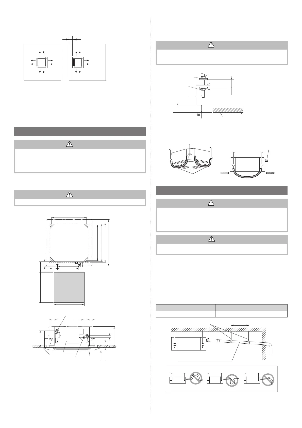
Discharge direction setting
• The discharge direction can be selected as shown below.
100 or more*
(4 directions) (3 directions)
(Unit: mm)
*Please ensure
suffi cient
service access
during installation.
• For a 3-way outlet, make sure to perform the Function Setting on the remote control.
Also, make sure to use the optional shutter plate to block the outlet.
• The ceiling height cannot be set in the 3-way outlet mode. Therefore, do not change the
setting in the setting the ceiling height. (Refer to “7. FUNCTION SETTING”)
• When the outlet is shut, be sure to install the optional Air outlet shutter plate kit.
For the details of installation, please refer to Installation Manual of kit.
3.3. Installing the unit
WARNING
• Install the air conditioner in a location which can withstand a load of at least 5 times the
weight of the main unit and which will not amplify sound or vibration. If the installation
location is not strong enough, the indoor unit may fall and cause injuries.
• If the job is done with the panel frame only, there is a risk that the unit will come loose.
Please take care.
3.3.1. Position the ceiling hole and hanging bolts
Ceiling openings and hanging bolt installation diagram.
WARNING
When fastening the hangers, make the bolt positions uniform.
(Unit: mm)
530 (Hanging bolt position)
service access
75
150 to 200
540 (Hanging bolt position)
570(Indoor unit)
580 to 610 (Ceiling openings)
620 (Cassette Grille)
Min.450
Min.450
135
250
99
40
102
215
30
58
123
114
30
262
Drain pipe (O.D.ø26.1)
Ceiling
Control box
Liquid pipe
Gas pipe
Be sure to keep suffi cient space in the designated position for future maintenance.
3.3.2. Body installation
(1) Install special nut A, then special nut B onto the hanging bolt.
(2) Raise the body and mount its hooks onto the hanging bolt between the special nuts.
(3)Turn special nut B to adjust the height of the body.
WARNING
• Perform fi nal tightening by tightening the double nut fi rmly.
• Be sure to install the body horizontally and adjust the height below the body and the
ceiling surface properly.
Special nut A
(accessories)
After installing the
body, tighten the nuts.
Hook
Ceiling
(Unit: mm)
30
or more
Special nut B
(accessories)
Hanging bolt
3.3.3. Leveling
Using a level, or vinyl hose filled with water, fine adjust so that the body is level.
Inclined installation so as the drain pipe side is higher may cause a malfunction of the float
switch, and may cause water leakage.
Vinyl hoses
Drain pipe
3.4. Drain installation
WARNING
• Do not insert the drain piping into the sewer where sulfurous gas occurs. (Heat ex-
change erosion may occur)
• Insulate the parts properly so that water will not drip from the connection parts.
• Check for proper drainage after installation by using the visible portion of transparent
drain port and the drain piping fi nal outlet on the body.
CAUTION
Do not apply adhesive agent on the drain port of the body. (Use the attached drain hose
assembly to connect the drain piping)
3.4.1. Installing the drain pipe
■
When not lifting up drain pipe:
• Install the drain pipe with downward gradient (1/50 to 1/100) and so there are no rises or
traps in the pipe.
• Use general hard polyvinyl chloride pipe (VP25) [outside diameter 32mm] and connect it
with adhesive (polyvinyl chloride) so that there is no leakage.
• When the pipe is long, install supporters.
• Do not perform air bleeding.
• Always heat insulate indoor section of drain pipe.
• If it is impossible to have suffi cient gradient of pipe, perform drain lift-up.
Pipe size
Drain pipe VP25 (O.D. 32 mm)
Hanging fi ttings
1.5 to 2 m
VP25 (O.D. 32 mm)
Downward gradient 1/100 to 1/50
Rise
PROHIBITED:
Trap
Air bleeding
9379124119-03_IM.indb 69379124119-03_IM.indb 6 2019/2/22 16:51:372019/2/22 16:51:37
 Loading...