En-14
6. REMOTE CONTROL INSTALLATION
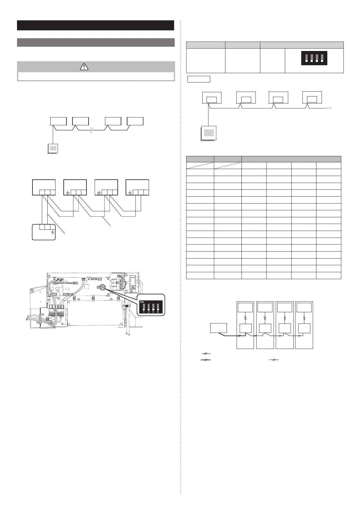
6.1. Group control
NOTES: Group control cannot be used together with W-LAN adapter.
CAUTION
Group control cannot be used when using it by the fl exible multi type.
A number of indoor units can be operated at the same time using a single remote controller.
*When different types of indoor units (such as wall mounted type and cassette type,
cassette type and duct type, or other combinations) are connected using group control
system, some functions may no longer be available.
(1) Connect up to 16 indoor units in a system. (indoor unit to remote controller)
A
BCDE
I.U. I.U. I.U. I.U.
Remote
controller
A, B, C, D, E : Remote controller cable.
A+B+C+D+E ≤ 500 m.
Example of wiring method (2-wire type)
123 123 123 123
123
Y
1 Y2
Indoor unit 1 Indoor unit 2 Indoor unit 3 Indoor unit 4
Remote controller cable
Remote controller cable
Remote controller
(2) Set the R.C. address (DIP switch setting)
Set the R.C. address of each indoor unit using the DIP switch on the indoor unit
circuit board.
SW100
(a) 2-wire type
DIP switch (RC AD SW)...Factory setting “00”
Since the remote controller address settings are automatically confi gured, you do not
need to confi gure them.
If confi guring manually, it is necessary to confi gure both the indoor unit and the remote
controller. For details, please refer to the remote controller installation manual.
(b) 3-wire type
DIP switch (RC AD SW)...Factory setting “00”
When connecting multiple indoor units to 1 standard wired remote controller, set the
address at RC AD SW in sequence from “00”.
Setting Setting range Switch 100
Remote controller
address
00 to 15
Setting
example 00
1234
ON
RC AD
Example
If 4 indoor units are connected.
RC AD SW
00
RC AD SW
01
RC AD SW
02
RC AD SW
03
Indoor unit 1
Remote
controller
Indoor unit 2 Indoor unit 3 Indoor unit 4
Set the R.C. address in accordance with the table below.
Indoor unit R.C. address DIP SWITCH No.
1234
1
00 OFF OFF OFF OFF
2
01 ON OFF OFF OFF
3
02 OFF ON OFF OFF
4
03 ON ON OFF OFF
5
04 OFF OFF ON OFF
6
05 ON OFF ON OFF
7
06 OFF ON ON OFF
8
07 ON ON ON OFF
9
08 OFF OFF OFF ON
10
09 ON OFF OFF ON
11 10 OFF ON OFF ON
12 11 ON ON OFF ON
13 12 OFF OFF ON ON
14 13 ON OFF ON ON
15 14 OFF ON ON ON
16
15 ON ON ON ON
NOTES:
Be sure to set consecutive R.C. address.
The indoor units cannot be operated if a number is skipped.
00 01 02 03
R.C. address
(DIP switch setting)
Remote
controller
: Transmission cable, Power supply cable
: Connection cable
: Remote controller cable
Outdoor
unit 1
Indoor
unit 1
Indoor
unit 2
Indoor
unit 3
Indoor
unit 4
Outdoor
unit 2
Outdoor
unit 3
Outdoor
unit 4
9379124119-03_IM.indb 149379124119-03_IM.indb 14 2019/2/22 16:51:382019/2/22 16:51:38
 Loading...