En-16
(2) Set the R.C. address (DIP switch setting)
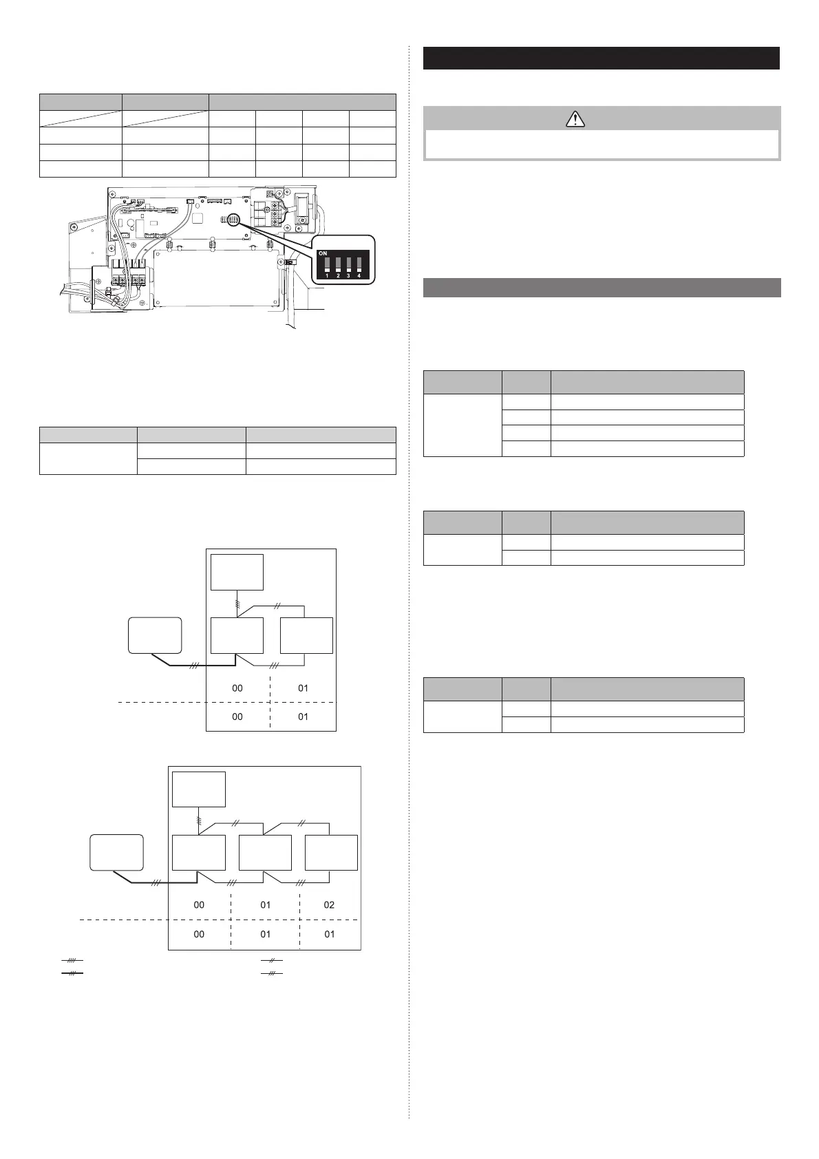
Set the R.C. address of each indoor unit using the DIP switches on the indoor unit
circuit board. (Refer to the following table and fi gure.)
The DIP switches are normally set to make the R.C. address “00”.
Indoor unit R.C. address DIP SWITCH No.
1234
1 00 OFF OFF OFF OFF
2 01 ON OFF OFF OFF
3 02 OFF ON OFF OFF
SW100
NOTES:
Be sure to set the R.C. address sequentially.
(3) Set the primary and secondary (Remote controller setting)
1. Turn on all of the indoor units.
2. Set the “primary” and “secondary” settings.
(Set the indoor unit that is connected to the outdoor unit using a connection cable
as the “primary”.)
Function number Setting value Setting description
51
00 Primary
01 Secondary
3. After completing the function settings, turn off all of the indoor units, and then turn
them back on.
* If error code 21, 22, 24 or 27 is displayed, there may be an incorrect setting.
Perform the remote controller setting again.
■
Twin type (18, 22, 24 model only)
R.C. address
Primary/Secondary setting
(DIP switch setting)
(Function number 51)
Outdoor
unit
Remote
controller
Indoor
unit 1
[Primary]
Indoor
unit 2
[Secondary]
■
Triple type (18 model only)
R.C. address
Primary/Secondary setting
(DIP switch setting)
(Function number 51)
Outdoor
unit
Remote
controller
: Transmission cable, Power supply cable
: Power supply cable
: Connection cable
: Remote controller cable
Indoor
unit 1
[Primary]
Indoor
unit 2
[Secondary]
Indoor
unit 3
[Secondary]
7. FUNCTION SETTING
Perform the Function setting according to the installation conditions using the remote
controller.
CAUTION
• Confi rm whether the wiring work for outdoor unit has been fi nished.
• Confi rm that the cover for the electrical enclosure on the outdoor unit is in place.
• This procedure changes to the Function settings used to control the indoor unit
according to the installation conditions. Incorrect settings can cause the indoor unit to
malfunction.
• After the power is turned on, perform the Function setting according to the installation
conditions using the remote controller.
• The settings may be selected between the following two: Function number or setting
value.
• Settings will not be changed if invalid numbers or setting values are selected.
7.1. Function details
■
Filter sign
Select appropriate intervals for displaying the fi lter sign on the indoor unit according to the
estimated amount of dust in the air of the room.
If the indication is not required, select “No indication” (03).
(♦... Factory setting)
Function
number
Setting
value
Setting description
11
00 Standard (2500 hours)
01 Long interval (4400 hours)
02 Short interval (1250 hours)
03 No indication ♦
■
Ceiling height
Select the appropriate ceiling height according to the place of installation.
(♦... Factory setting)
Function
number
Setting
value
Setting description
20
00 Standard (2.7m)
♦
01 High ceiling (3.0m)
In case of Cassette type models:
The ceiling height values are for the 4-way outlet.
Do not change this setting in the 3-way outlet mode.
7000, 9000 Btu/h models cannot be installed in high ceilings.
Do not change this setting.
■
Outlet directions
Select the appropriate number of outlet directions according to the installation conditions.
(♦... Factory setting)
Function
number
Setting
value
Setting description
22
00
4-way ♦
01
3-way
9379124119-03_IM.indb 169379124119-03_IM.indb 16 2019/2/22 16:51:382019/2/22 16:51:38
 Loading...