En-12
(2) Connect the connector.
Cable (louver): WHITE
Cable (display): WHITE
Cable (louver): RED
Indoor unit side
• Arrange the cables as illustrated below.
(3) Attach the connector cover.
Screw
Connector cover
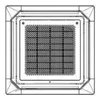
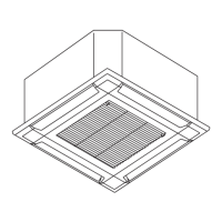
4.3. Attach the intake grille
The installation is the reverse of “REMOVING THE INTAKE GRILLE”.
The intake grille can be rotated and installed 4 ways to suit the user’s preference.
CAUTION
• The louver angle cannot be changed if the power is not on. (If moved by hand, it may
be damaged.)
• The grille assembly is directionally relative to the air conditioner body.
• Install so that there is no gap between the grille assembly and the air conditioner
body.
• The cassette grille equips with an accessory to prevent the grill completely open.
Be sure to read the INSTALLATION SHEET included with the cassette grille before
installation.
5. OPTIONAL INSTALLATION WORK
5.1. Optional kit installation
WARNING
Regulation of cable differs from each locality, refer in accordance with local rules.
Terminal (External input)Remote controller cable
CN47 CN65
CN46
This air conditioner can be connected with the following optional kits.
For details on how to install optional parts, refer to the installation manual included in each
item.
Connector No. Option type
― Wired remote controller
CN46 External input (PCB Terminal)
CN47 Fresh air intake kit (UTZ-VXAA) External output (UTY-XWZXZG) [*1]
CN65 [*2] Other optional parts
*1: For external output terminal setting, refer to Function No.60 in “7. FUNCTION SET-
TING”.
*2: Other options (WLAN adapter, converters, etc.) may be connectable. Please refer to
the technical data for details.
NOTES:
Options connecting to CN47 or CN65 cannot be used at the same time.
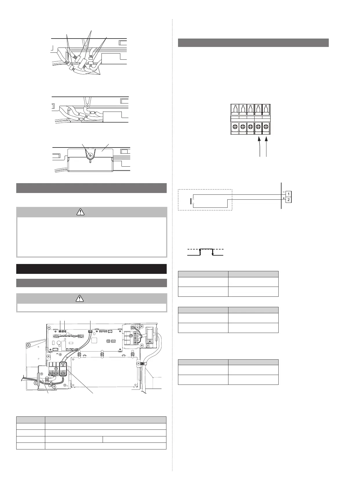
5.2. External input and output
5.2.1. External input
• Indoor unit functions such as Operation/Stop or Forced stop can be done by using
indoor unit terminals.
• “Operation/Stop” mode or “Forced stop” mode can be selected with function setting of
indoor unit.
•
A twisted pair cable (22 AWG) should be used. Maximum length of cable is 150 m (492 ft.).
• Use an external input and output cable with appropriate external dimension, depending
on the number of cables to be installed.
• The wire connection should be separate from the power cable line.
Y1 Y2
TO REMOTE CONTROL UNIT Ex IN
Y3 1 2
Connected device
Terminal
● Dry contact terminal
When a power supply is unnecessary at the input device you want to connect, use the Dry
contact terminal.
*1
Terminal
(External in)
Connected device
*1: The switch can be used on the following condition: DC 12 V to 24 V, 1 mA to 15 mA.
■
Operation behavior
● Input signal type
Edge
ON
OFF
When function setting is “Operation/Stop” mode 1.
Input signal Command
OFF → ON Operation
ON → OFF Stop
When function setting is “Forced stop” mode.
Input signal Command
OFF → ON Forced stop
ON → OFF Normal
* When the forced stop is triggered, indoor unit stops and Operation/Stop operation by a
remote controller is restricted.
When function setting is “Operation/Stop” mode 2.
Input signal Command
OFF → ON Operation
ON → OFF Stop (R.C. disabled)
9379124119-03_IM.indb 129379124119-03_IM.indb 12 2019/2/22 16:51:382019/2/22 16:51:38
 Loading...