En-7
NOTES:
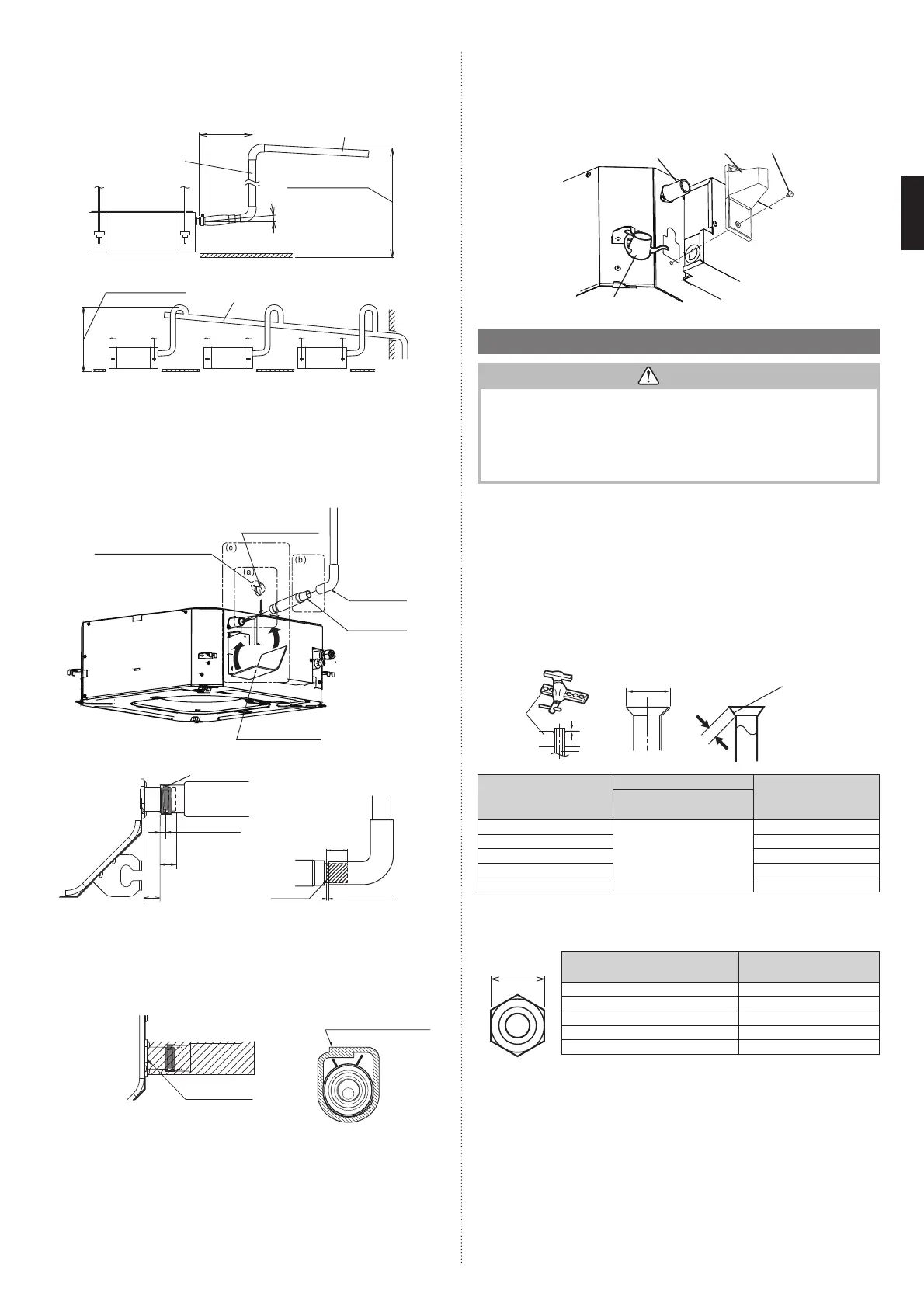
Check for drainage
Pour about 1 liter of water from the position shown in the diagram or from the airfl ow outlet
to the dew tray. Check for any abnormalities such as strange noises and whether the drain
pump functions normally
The drain pump operates when operating in the cooling mode.
Drain pipe Wire cover
Screw
Watering pot
3.5. Pipe installation
CAUTION
• Tighten the fl are nuts with a torque wrench using the specifi ed tightening method.
Otherwise, the fl are nuts could break after a prolonged period, causing refrigerant to
leak and generate hazardous gas if the refrigerant comes into contact with a fl ame.
• Be careful that foreign matter (oil, water, etc.) does not enter the piping with refriger-
ant R32(R410A) models. Also, when storing the piping, securely seal the openings
by pinching, taping, etc.
• While brazing the pipes, be sure to purge with dry nitrogen gas.
3.5.1. Pipe connection
■
Flaring
Use special pipe cutter and fl are tool designed for R410A or R32 pipework.
(1) Cut the connection pipe to the necessary length with a pipe cutter.
(2) Hold the pipe downward so that cuttings will not enter the pipe and remove any burrs.
(3) Insert the fl are nut (always use the fl are nut attached to the indoor unit(s) and outdoor
unit or branch box respectively) onto the pipe and perform the fl are processing with a
fl are tool. Use the special R410A or R32 fl are tool, or the conventional fl are tool. Leak-
age of refrigerant may result if other fl are nuts are used.
(4) Protect the pipes by pinching them or with tape to prevent dust, dirt, or water from
entering the pipes.
Die
A
Pipe
B
L
Check if [L] is flared uniformly
and is not cracked or scratched.
Pipe outside diameter
[mm (in.)]
Dimension A [mm]
Dimension B [mm]
Flare tool for R32,
clutch type
6.35 (1/4)
0 to 0.5
9.1
9.52 (3/8) 13.2
12.70 (1/2) 16.6
15.88 (5/8) 19.7
19.05 (3/4) 24.0
When using conventional fl are tools to fl are R32 pipes, the dimension A should be approx-
imately 0.5 mm more than indicated in the table (for fl aring with R32 fl are tools) to achieve
the specifi ed fl aring. Use a thickness gauge to measure the dimension A.
Width across
flats
Pipe outside diameter [mm (in.)]
Width across flats
of Flare nut [mm]
6.35 (1/4) 17
9.52 (3/8) 22
12.70 (1/2) 26
15.88 (5/8) 29
19.05 (3/4) 36
NOTES: The fl are nut specifi cation is compliant with ISO14903.
■
When lifting up drain pipe:
• Height of inclined pipe should be less than 700 mm from the ceiling. A rise dimension
over this range will cause leakage.
• Lift up the pipe vertically at the position of 300 mm or less from the unit.
300 mm or less
VP25 (O.D. 32 mm)
local arrangement
700 mm or less
Horizontal or
upward gradient
Downward gradi-
ent 1/100 to 1/50
VP30 (O.D. 38 mm) or more
Downward gradient 1/100 to 1/50
700 mm or less
3.4.2. Installation procedure
1) Install the attached drain hose to the drain port of the body. Install the hose band from
the top of the hose within the shown in the fi gure area.
2) Use vinyl adhesive agent to glue the drain piping (PVC pipe VP25 ) to the drain hose
assembly.
(Apply color adhesive agent evenly until the gauge line and seal)
3) Check the drainage. (Refer to separate diagram)
4) Install the heat insulation.
5) Use the attached heat insulation to insulate the drain port and hose band.
Install the knob facing upward
Attach hose band
(Accessories)
Locally installed
PCV pipe
Attach drain hose
(Accessories)
Attach heat insulation
(Accessories)
・
(a) Top view
(c) Hose opening view
Top view
(b) Side view
Hose band
19
Applying area
of adhesive 35
(Unit: mm)
Gauge line
4 or less
20 Transparent
visible portion
Make sure there
are no gaps
Wind the attached heat
insulation around the
hose band make sure
the alignment is on top
5~10
20
9379124119-03_IM.indb 79379124119-03_IM.indb 7 2019/2/22 16:51:372019/2/22 16:51:37
 Loading...