En-18
■
Setting record
Record any changes to the settings in the following table.
Setting description Setting value
Filter sign
Ceiling height
Outlet directions
Room temperature control for indoor
unit sensor
Cooling
Heating
Room temperature control for wired
remote controller sensor
Cooling
Heating
Auto restart
Room temperature sensor switching
Remote controller custom code
External input control
Room temperature sensor switching (Aux.)
Indoor unit fan control for energy saving for cooling
Switching functions for external output terminal
After completing the Function Setting, be sure to turn off the power and turn it on again.
8. CHECK LIST
Pay special attention to the check items below when installing the indoor unit(s). After instal-
lation is complete, be sure to check the following check items again.
CHECK ITEMS If not performed correctly CHECK BOX
Has the indoor unit been installed
correctly?
Vibration, noise, indoor unit may
drop
Has there been a check for gas
leaks (refrigerant pipes)?
No cooling, No heating
Has heat insulation work been com-
pleted?
Water leakage
Does water drain easily from the
indoor units?
Water leakage
Are the wires and pipes all con-
nected completely?
No operation, heat or burn dam-
age
Is the connection cable the specified
thickness?
No operation, heat or burn dam-
age
Are the inlets and outlets free of any
obstacles?
No cooling, No heating
After installation is completed, has
the proper operation and handling
been explained to the user?
9. TEST RUN
9.1. Check items
□ Is operation of each button on the remote controller normal?
□ Does each lamp light normally?
□ Is the drain normal?
□ Do not have an abnormal noise and vibration during operation?
Do not operate the air conditioner in test run for a long time.
9.2. Operation method
Depending on your installation, choose from the following:
■
By the wireless remote controller (with [TEST RUN] button)
(1) To start test run, press [START/STOP] and [TEST RUN] on the remote controller.
(2) To end test run, press [START/STOP] on the remote controller.
■
By the indoor unit or IR receiver unit
(1) To start test run, press [MANUAL AUTO] of the unit for more than 10 seconds (forced
cooling).
(2)
To end test run, press [MANUAL AUTO] for more than 3 seconds or press [START/STOP]
on the remote controller.
The Operation indicator lamp and Timer indicator lamp will simultaneously fl ash during
the test run mode.
■
By the wired remote controller
(1) For the operation method, refer to the installation manual and the operating manual of
the wired remote controller.
Heating test run will begin in a few minutes when HEAT is selected by the remote control-
ler [reverse cycle model only].
10. FINISHING
10.1. Installing heat insulation
CAUTION
• After checking for gas leaks (refer to the Installation Manual of the outdoor unit),
perform this section.
• Install heat insulation around both the large (gas) and small (liquid) pipes. Failure to
do so may cause water leaks.
• Must fi t tightly against body without any gap.
After checking for gas leaks, insulate by wrapping insulation around the 2 parts (gas and
liquid) of the indoor unit coupling, using the Coupler Heat Insulation.
After installing the Coupler Heat Insulation, wrap both ends with vinyl tape so that there is
no gap.
Coupler heat insulation
Coupler heat
insulation
Be sure to overlap the
insulation
No gap
No gap
Body
11. CUSTOMER GUIDANCE
Explain the following to the customer in accordance with the operating manual:
(1) Starting and stopping method, operation switching, temperature adjustment, timer, air
fl ow switching, and other remote controller operations.
(2) Cleaning and maintenance of the product, and other items such as air fi lters and air
louvers if applicable.
(3) Give the operating and installation manuals to the customer.
(4) If the indoor unit custom code is changed, and the installation includes a wireless remote
controller, inform the customer the changed code. (On some wireless remote controllers,
the custom code may return to A when batteries are replaced.)
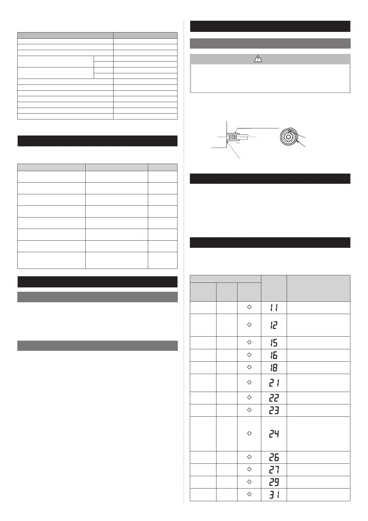
12. ERROR CODES
If you use a wireless remote controller, the lamp on the photo detector unit will output error
codes by way of blinking patterns. If you use a wired remote controller, error codes will ap-
pear on the remote control display. Refer to the lamp blinking patterns and error codes in
the table. An error display is displayed only during operation.
Error display
Error code Description
OPERATION
lamp
(green)
TIMER
lamp
(orange)
ECONOMY
lamp
(green)
(1)
(1)
Serial communication error
(1)
(2)
• Wired remote controller
communication error
• Server room control
communication error
(1)
(5)
Check run unfinished
Automatic airflow adjustment error
(1)
(6)
Peripheral unit transmission PCB
connection error
(1)
(8)
External communication error
(2)
(1)
Unit number or Refrigerant circuit
address setting error
[Simultaneous Multi]
(2)
(2)
Indoor unit capacity error
(2)
(3)
Combination error
(2)
(4)
• Connection unit number
error (indoor secondary unit)
[Simultaneous Multi]
• Connection unit number error
(indoor unit or branch unit)
[Flexible Multi]
(2)
(6)
Indoor unit address setting error
(2)
(7)
Primary unit, secondary unit setup
error [Simultaneous Multi]
(2)
(9)
Connection unit number error in
wired remote controller system
(3)
(1)
Power supply interruption error
9379124119-03_IM.indb 189379124119-03_IM.indb 18 2019/2/22 16:51:382019/2/22 16:51:38
 Loading...