En-5
2.4. Pipe requirement
Model Gas pipe size (thickness) [mm] Luquid pipe size (thickness) [mm]
07, 09, 12, 14 Ø 9.52 (0.80) Ø 6.35 (0.80)
18, 22, 24 Ø 12.70 (0.80) Ø 6.35 (0.80)
CAUTION
Refer to the installation manual for the outdoor unit for description of allowable pipe
length and height difference.
• Use pipe with water-resistant heat insulation.
CAUTION
• Wrap heat insulation around both gas pipe and liquid pipe.
No heat-insulation work or incorrect heat-insulation work may cause water leaks.
• In a reverse cycle model, use heat insulation with heat resistance above 120 °C.
• If expected humidity of the installation location of refrigerant pipes is higher than
70 %, wrap the heat insulation around the refrigerant pipes.
If the expected humidity is between 70 % and 80 %, use heat insulation that has
a thickness of 15 mm or more.
If the expected humidity is higher than 80 %, use heat insulation that has a thickness
of 20 mm or more.
• The use of thinner heat insulation than specifi ed above, may cause a condensation
on the surface of the insulation.
• Use heat insulation with thermal conductivity of 0.045 W/(
m•K
) or less, at 20
°C
.
2.5. Electrical requirement
The indoor unit is powered from the outdoor unit. Do not power indoor unit from separate
power source.
WARNING
Standard for electrical wiring and equipment differs in each country or region. Before you
start electrical working, confi rm related regulations, codes, or standards.
Cable
Conductor size [
mm
2
] Type
Remarks
Connection cable
1.5 (Min) Type 60245 IEC 57
3 cable + Earth (Ground),
1 Ø 230 V
Cable Length: Limit voltage drop to less than 2%. Increase cable gauge if voltage drop is
2% or more.
2.6. Optional parts
Refer to each installation manual for the method of installing optional parts.
Wired remote controller (*1)
UTY-RNR*Z*
For air conditioner operation
(2-wired type)
UTY-RLR*
UTY-RVN*M
For air conditioner operation
(3-wired type)
UTY-RNN*M
Wireless remote controller UTY-LNT* For air conditioner operation
Fresh air intake kit UTZ-VZAA To take fresh air
Air outlet shutter plate UTR-YDZB
Install the plate at outlet when carrying
out 3-way direction operation
Insulation kit for High hu-
midity
UTZ-KXGC
Install when the condition under the roof
is over 80% in humidity and over 30
°C
in
temperature.
External connect kit
PCB terminal For control input port
UTY-XWZXZG For control output port
W-LAN interface UTY-TFSXZ1
For wireless LAN control
*1: Wired remote controller is recommended using simultaneous twin or triple connection.
3. INSTALLATION WORK
WARNING
Do not move the appliance by holding the indoor unit pipes.
(The stress applied to the pipe joints may cause the fl ammable gas to leak during
operation.)
Especially, the installation place is very important for the split type air conditioner because
it is very diffi cult to move from place to place after the fi rst installation.
3.1. Selecting an installation location
WARNING
Select installation locations that can properly support the weight of the indoor unit.
Install the units securely so that they do not topple or fall.
CAUTION
• Do not install the unit in the following areas:
- Area with high salt content, such as at the seaside. It will deteriorate metal parts,
causing the parts to fail or the unit to leak water.
- Area fi lled with mineral oil or containing a large amount of splashed oil or steam,
such as a kitchen. It will deteriorate plastic parts, causing the parts to fail or the
unit to leak water.
- Area where is close to heat sources.
- Area that generates substances that adversely affect the equipment, such as
sulfuric gas, chlorine gas, acid, or alkali. It will cause the copper pipes and brazed
joints to corrode, which can cause refrigerant leakage.
- Area that can cause combustible gas to leak, contains suspended carbon fi bers or
fl ammable dust, or volatile in fl ammables such as paint thinner or gasoline.
- If gas leaks and settles around the unit, it can cause a fi re.
- Area where animals may urinate on the unit or ammonia may be generated.
• Do not use the unit for special purposes, such as storing food, raising animals, grow-
ing plants, or preserving precision devices or art objects. It can degrade the quality
of the preserved or stored objects.
• Install the unit where drainage does not cause any trouble.
• Do not install where there is the danger of combustible gas leakage.
• Do not install the unit near a source of heat, steam, or fl ammable gas.
• Install the indoor unit, outdoor unit, power supply cable, transmission cable, and
remote control cable at least 1 m away from a television or radio receivers. The
purpose of this is to prevent TV reception interference or radio noise.
(Even if they are installed more than 1 m apart, you could still receive noise under
some signal conditions.)
• If children under 10 years old may approach the unit, take preventive measures so
that they cannot reach the unit.
• Use the “Insulation kit for high humidity” (option), when the condition under the roof
is over 80% in humidity and over 30°C in temperature. Otherwise, there is a risk of
condensation on the ceiling.
Decide the mounting position together with the customer as follows:
(1) Install the indoor unit in a location having suffi cient strength to support the weight of
the indoor unit.
(2) The inlet and outlet ports should not be obstructed; the air should be able to blow all
over the room.
(3) Leave the space required to service the air conditioner.
(4) Locate where the air can be distributed evenly throughout the room by the unit.
(5) Install the unit where connection to the outdoor unit is easy.
(6) Install the unit where the connection pipe can be easily installed.
(7) Install the unit where the drain pipe can be easily installed.
(8) Install the unit where noise and vibration is not amplifi ed.
(9) Take servicing, etc., into consideration and leave the spaces. Also install the unit
where the fi lter can be removed.
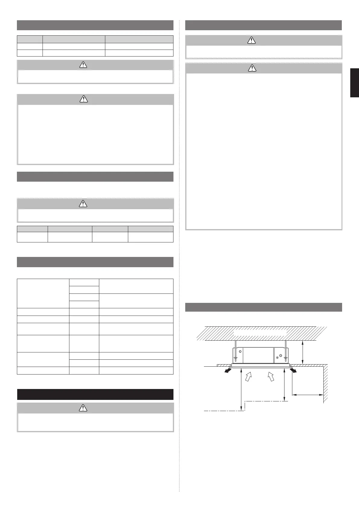
3.2. Installation dimensions
• The ceiling rear height as shown in the fi gure.
Strong and durable ceiling
262 or
more
1,000 or
more
1,800 or
more
1,000 or
more
(Unit: mm)
Floor
Obstruction
• This product can be installed at a height of up to 3,000mm.
However, 7000, 9000 Btu/h model can not be installed in high places.
Perform the Function Setting on the remote control in accordance with the installed height.
(Refer to
“7. FUNCTION SETTING”)
9379124119-03_IM.indb 59379124119-03_IM.indb 5 2019/2/22 16:51:372019/2/22 16:51:37
 Loading...