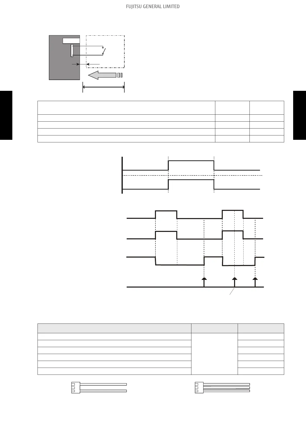
• Circuit diagram example
Indoor unit
control PCB
*1
Example: Switch
Locally purchased
Connected unit
1
3
Signal
10 m*2
Connector
• Contact capacity: DC 24 V or more, 10 mA or more.
• *1: PCB of Communication kit is used for wall mounted
type .
• *2: Make the distance from the PCB to the connected
unit within 10 m.
• Use non-polar relays and switches.
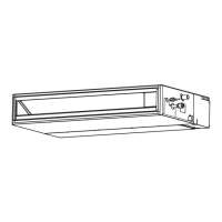
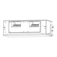
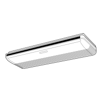
Indoor unit type
1-pin 3-pin
(Polarity) (Polarity)
Compact cassette and Cassette - +
Slim duct and Duct - +
Floor/Ceiling - +
Ceiling - +
– When function setting is "Operation/Stop" mode
Operation
Stop
On
Off
Input signal
Indoor unit
– When function setting is "Forced stop" mode
Remote controller
On On On
Input signal
Indoor unit
Command
Remote control
operation invalidity
On
Off
Operation
Stop
Forced stop
Normal
• Optional part
Indoor unit type Part name Model name
Compact cassette
External connect
kit
UTY-XWZX
Cassette UTY-XWZX
Slim duct UTD-ECS5A
Duct UTD-ECS5A
Floor/Ceiling UTY-XWZX
Ceiling UTY-XWZX
UTY-XWZX UTD-ECS5A
- 227 -
6-1. Indoor unit 6. External input and output
SYSTEM
DESIGN
SYSTEM
DESIGN
 Loading...