6-2. Outdoor unit
Connector Input Output Remarks
CN131 Low noise mode —
For details, refer to external input and
output settings.
CN132 Peak cut mode —
CN136 — Error status
CN137 — Compressor status
¢
External input
With using external input function, on/off status of “Low noise mode” and “Peak cut mode” can be
specified by the external signal.
Low noise mode
In following condition, the operating noise of the outdoor unit reduces comparing from the one in nor-
mal operating condition:
The air conditioner is set to the “Low noise mode” when closing the contact input of a commercial
timer or on/off switch to a connector on the control PCB of the outdoor unit.
NOTE: Product performance may drop depending on some conditions such as the outdoor temper-
ature.
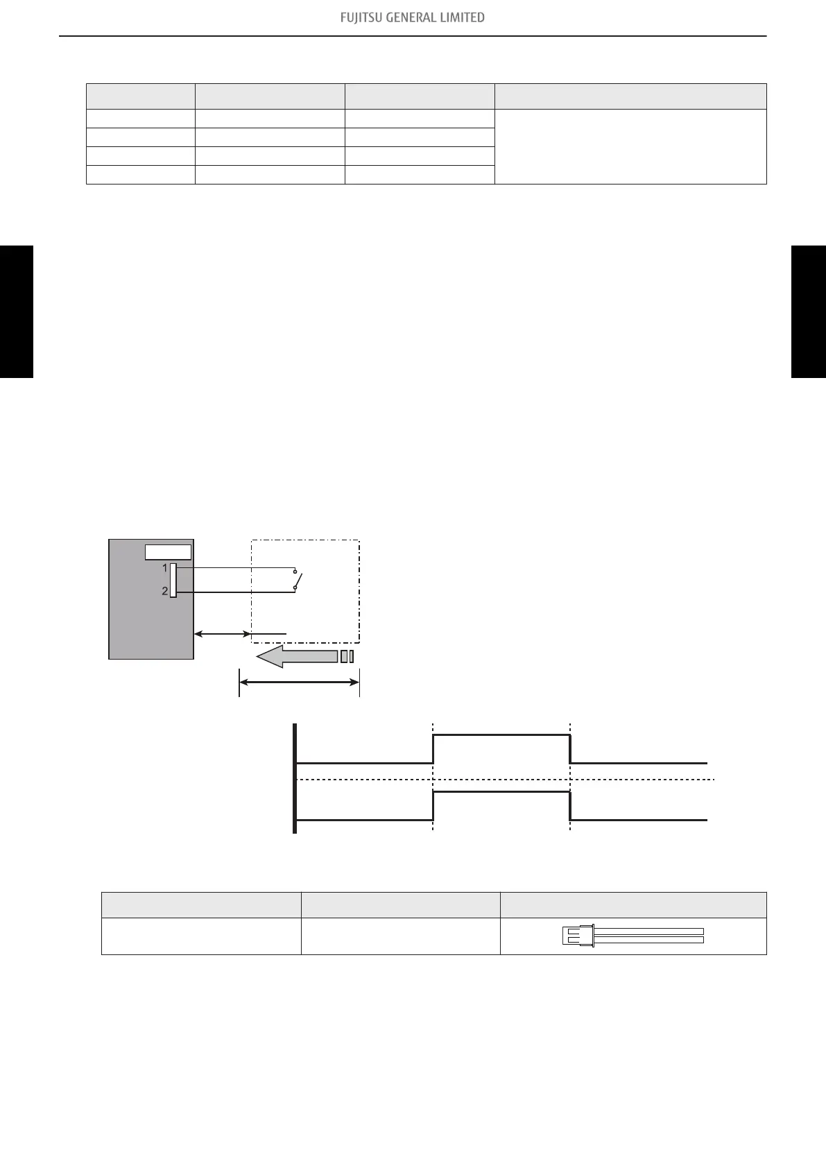
• Circuit diagram example (CN131)
Outdoor unit
control PCB
Connected unit
Example: Switch
Signal
*10 m
Connector
Locally purchased
CN131
• Contact capacity: DC 24 V or more, 10 mA or more.
• *: Make the distance from the PCB to the connected
unit within 10 m.
• Construct a circuit as shown in this figure with using op-
tional parts mentioned below.
• Input signal: On in “Low noise mode”
• Input signal: Off in normal operation
• To set the level of “Low noise mode”, refer to "Low
noise mode" on page 282.
On
Off
On
Off
Input signal
Low noise mode
• Optional part
Part name Model name Exterior
External connect kit UTY-XWZXZ3
- 232 -
6-2. Outdoor unit 6. External input and output
SYSTEM
DESIGN
SYSTEM
DESIGN
 Loading...