Peak cut mode
By performing following on-site work, operation that suppresses the current value can be enabled:
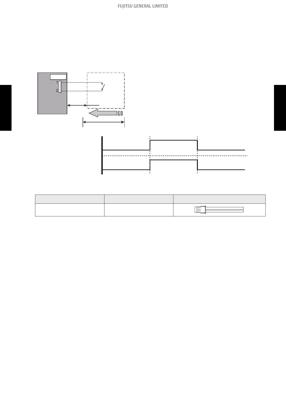
The air conditioner is set to the “Peak cut mode” when closing the contact input of a commercial
timer or on/off switch to a connector on the control PCB of the outdoor unit.
• Circuit diagram example (CN132)
Outdoor unit
control PCB
Connected unit
Example: Switch
Signal
*10 m
Connector
Locally purchased
CN132
• Contact capacity: DC 24 V or more, 10 mA or more.
• *: Make the distance from the PCB to the connected
unit within 10 m.
• Construct a circuit as shown in this figure with using op-
tional parts mentioned below.
• Input signal: On in “Peak cut mode”
• Input signal: Off in normal operation
• To set the level of “Peak cut mode”, refer to "Peak cut
mode" on page 283.
On
Off
On
Off
Input signal
Peak cut mode
• Optional part
Part name Model name Exterior
External connect kit UTY-XWZXZ3
- 233 -
6-2. Outdoor unit 6. External input and output
SYSTEM
DESIGN
SYSTEM
DESIGN
 Loading...