36 Operating Manual BX920 S2
Connecting devices
© cognitas. Gesellschft für Technik-Dokumentation mbH 2010 Pfad: C:\Programme\FCT\tim_app\tim_local\work\WALTER\OBJ_DOKU-5780-001.fm
4.3 Connecting devices
All connections that are required to operate the server blade are made via the
midplane of the PRIMERGY BX900 system unit. When the server blade is
installed, midplane contacts automatically establish connections to the
infrastructure modules on the rear of the system unit:
– Power supply units
– Management blade(s) for server administration
– Ethernet and/or fiber-channel connection blades for connection to a LAN or
SAN
You can find information about the external connectors of the BX900 system
unit in the relevant operating manual.
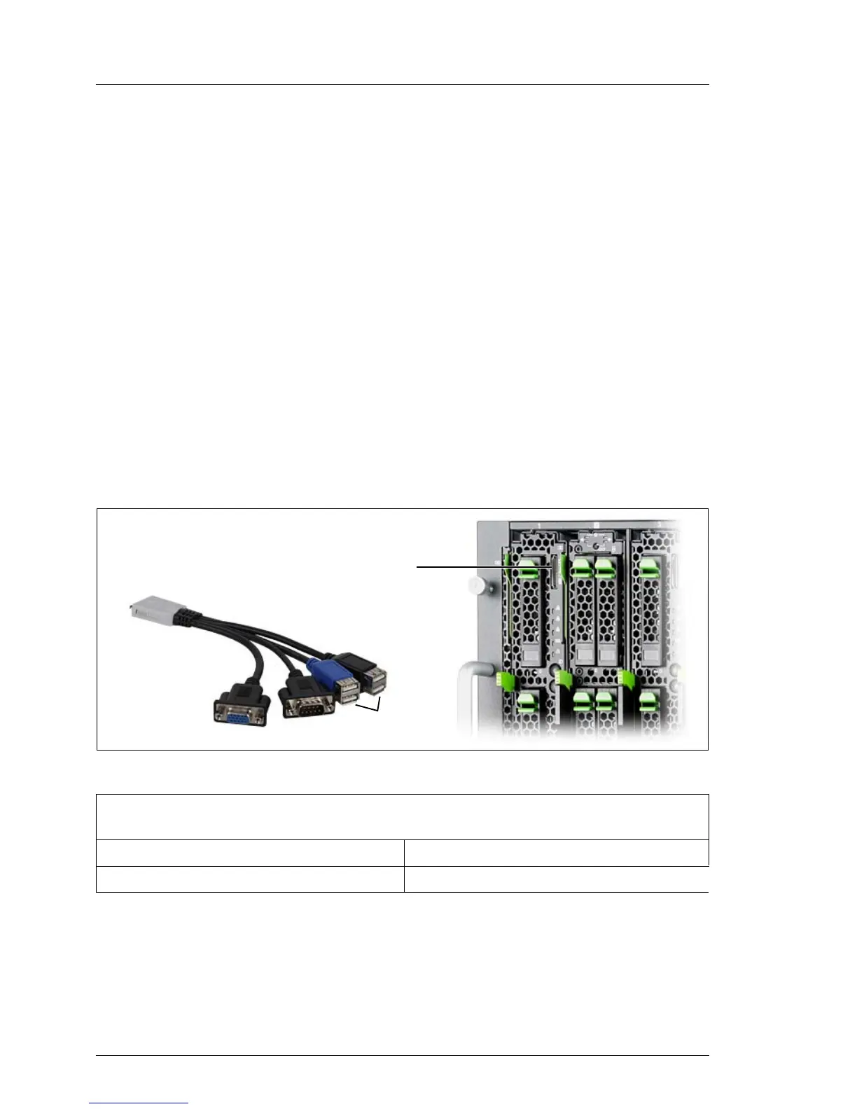
The front of the server blade has a connector for a special Y cable, which
provides 4 USB connectors, 1 video connector (VGA) and 1 serial connector.
Figure 5: Connectors on the front
I The Y cable is delivered with the system unit.
1 Plug connection to the server blade. The labeled side of the plug must face left when
plugged in.
2 Video connector (VGA) 3 Serial connector
4 USB connectors (4x) 5 Y cable connector on the server blade
Table 2: External connectors on the front
/
0
1
2
3
 Loading...