Questions? Please Contact Your Local Manufacturer’s Representative
SECTION 2 EDR-SOLA-IOM-2022-0216 INSTALLATION
2-19
Multiple Boilers Sharing A Common Drain Trap
The multiple boiler condensate drain trap is Fulton Part Num-
ber 4-57-000440. The maximum number of units to attach per
condensate drain trap is 12mm BTU total. (See Figures 14 and
16).
Adhere to the following for installation:
1. The Fulton Endura boiler 1 inch (25.4 mm) condensate
drain will be connected to the 1 inch (25.4 mm) inlet
on the drain trap. One or more drain lines may be
connected to this inlet (max of 12 MM BTU per drain).
2. If the water supply must be temporarily disconnected,
the boilers must be turned o to prevent accidental ue
gas emission into the boiler room.
3. The condensate drain cover must be kept on at all
times, except during maintenance of the drain. This
drain should be checked regularly in your boiler
maintenance schedule.
4. A condensate collecting tank and condensate pump
will be required if a oor drain is not available to collect
condensate (collecting tank and pump are not supplied
with the boiler.)
5. All piping (Figure 14) must be CPVC, galvanized, or
stainless steel, and be free of leaks. Copper, carbon
steel/iron pipe or PVC are not acceptable.
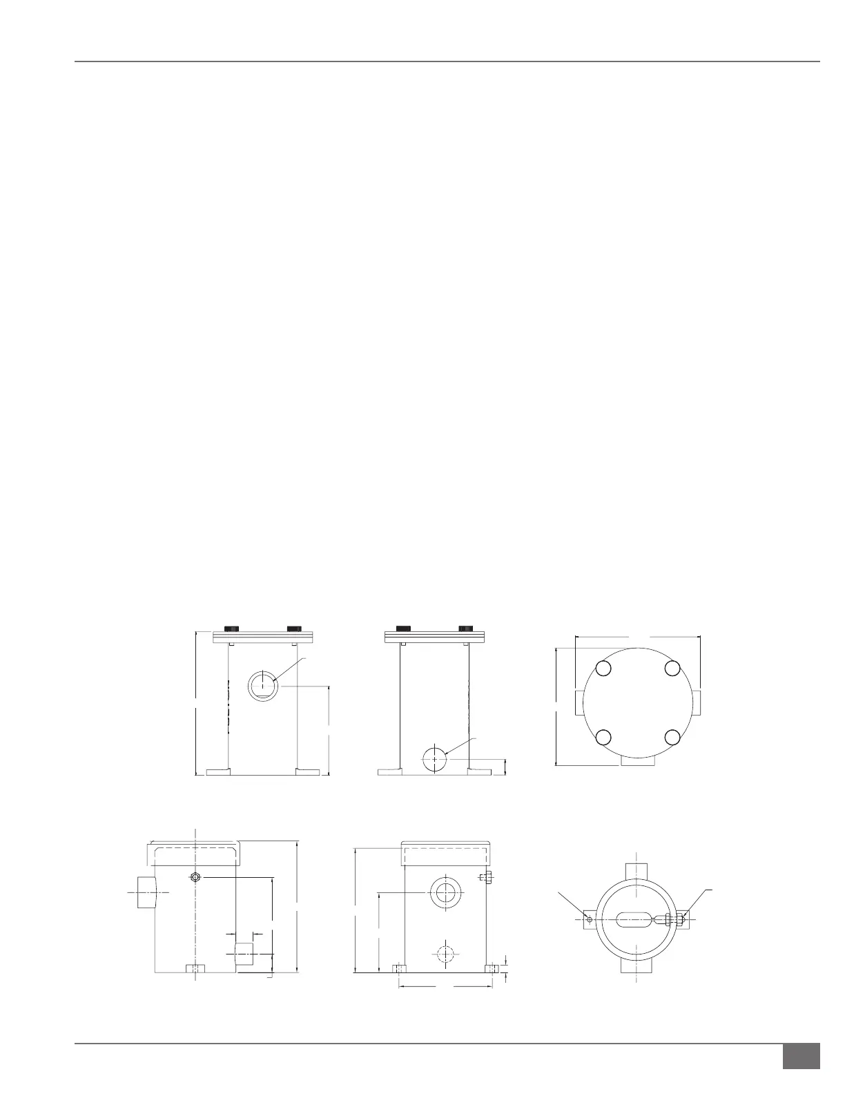
FIGURE 15 SINGLE BOILER CONDENSATE DRAIN TRAP
RIGHT SIDE VIEW
1 ½
1
7 ¾
10
10
6 ½
7
FRONT VIEWTOP VIEW
(COVER NOT SHOWN)
" (TYP. )
¼"
WATER SUPPLY
CONNECTION
FIGURE 16 MULTIPLE BOILER CONDENSATE DRAIN TRAP
FRONT VIEWBACK VIEWTOP VIEW
6½
" NPT
" NPT
4
5
4
6. Connect 1 inch (25.4 mm) condensate drain(s) (at the
rear of the boiler), to the 1 inch (25.4 mm) inlet at the
base of the drain tank. The header must be below
the condensate outlet of the boiler, and must remain
ooded during operation.
7. Connect the 1.5 inch (38.1 mm) drain outlet to an
appropriate waste line following applicable codes. The
1.5 inch (38.1 mm) drain connection on the drain tank
must be the highest point prior to going to the drain.
Failure to keep drain piping lower than this point will
result in overow of the drain tank. Slope the drain
pipe away at a minimum pitch of 1 inch (25.4 mm) for
every 12 feet (3.65 m).
8. Attach a ¼” water supply to the compression tting
on the oat. The water line must be connected to
an uninterruptible supply. Fulton recommends
connecting it before the “fast ll” valve to the boiler
supply but after the back ow preventer to avoid
contamination of a potable water supply. Maximum
allowable water pressure to the compression tting is
100 PSI (689.5 kPa).
NOTE: Ensure piping will not be exposed to freezing
temperatures.
 Loading...