Questions? Please Contact Your Local Manufacturer’s Representative
3-25
SECTION 3 EDR-SOLA-IOM-2022-0216 OPERATION
! WARNING
All information in this manual is for
reference and guidance purposes,
and does not substitute for required
professional training, conduct,
and strict adherence to applicable
jurisdictional/professional codes and
regulations.
Non-Fulton product information is for
reference purposes only. No Fulton
document may substitute for full
review of documentation available
from the component manufacturer.
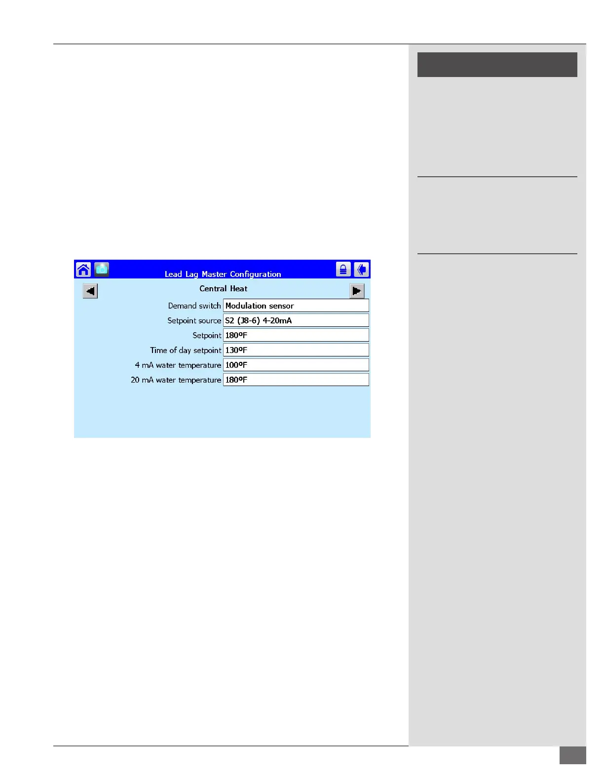
To establish the setpoint source for a lead lag boiler plant start from the boiler
status screen and select conguration. From the conguration screen scroll to
and select lead lag master conguration and select the box labeled advanced
settings in the bottom right hand corner. Using the left and right arrow keys scroll
to the screen labeled central heat. The row labeled Setpoint Source needs to be
set on S2 (J8-6) 4-20mA. Refer to Figure 61 for factory default settings:
O Hysteresis: The dierential above setpoint when the boiler is turned o.
On Hysteresis: The dierential from setpoint when the boiler is turned on.
4 mA water temperature: The setpoint valued assigned to a remote 4 mA
signal
20 mA water temperature: The setpoint valued assigned to a remote 20
mA signal
For a standalone boiler the remote signal for setpoint must be congured
through a dierent screen. From the boiler status screen select congure and
scroll to and select central heat conguration. Using the left and right arrow keys
scroll to the screen labeled setpoint.
Supply Header Temperature Sensor
The supply header temperature sensor is to be congured on the master boiler
only or a standalone boiler that may require a header sensor for modulation. For
further details on a standalone boiler application requiring a header sensor refer
to the supply header temperature sensor section of the electrical connections
and devices section. To congure a header temperature sensor start at the boiler
status screen. Select congure and scroll to and select sensor conguration. The
row labeled “*S5 (J8-11) Sensor” needs to be set at 10K NTC single non-safety. See
Figure 62.
For a lead/lag boiler plant the header temperature sensor will be referenced for
modulation by default. There is no additional conguration for the supply header
sensor in a lead lag boiler plant.
FIGURE 61 CENTRAL HEAT CONFIGURATION SETPOINT
 Loading...