© Fulton Group N.A., Inc. 2022
3-30
OPERATION EDR-SOLA-IOM-2022-0216 SECTION 3
From the boiler pump conguration screen select the advanced box in the
bottom right hand corner. Check only the boxes shown in Figure 70. Once this
has been done the pump conguration has been completed.
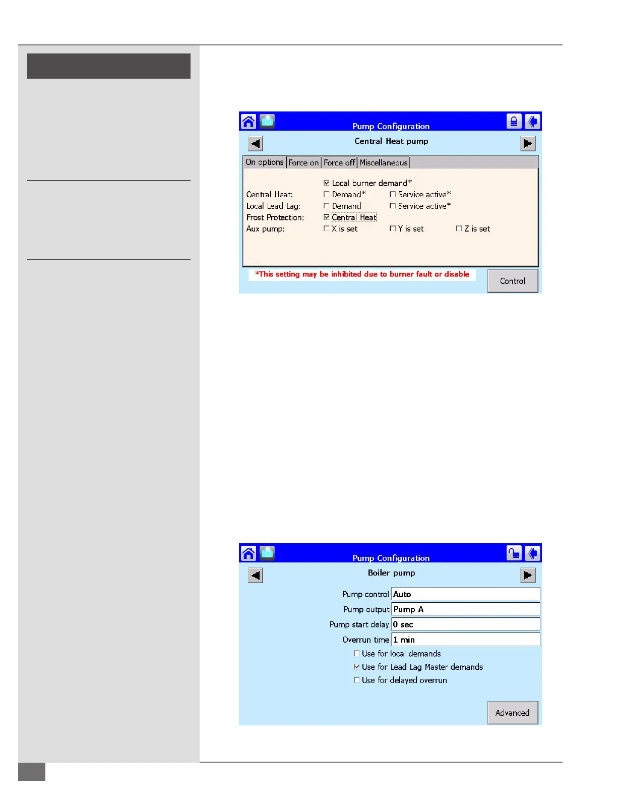
Motorized Isolation Valve Set Up
Motorized isolation valve conguration is only applicable to lead lag boiler plants
utilizing two-position motorized isolation valves. Starting from the status screen
tap congure and then select the pump conguration. From the pump congure
screen shown in Figure 71 below you will be able to congure the boiler plants
motorized isolation valve control. Any one of the available pump outputs A
through C can be used to do so. For Endura boilers equipped with an isolation
valve control relay, choose the pump output wired to this relay. From this screen
select Auto for pump control and either pump A, B, or C for pump output. The
“Use for Lead Lag Master Demands” box should be the only box selected out of
the three available. Refer to Figure 71 for factory default settings.
Pump Start Delay: The motorized valve will remain closed for this set time
upon demand.
Overrun Time: The motorized valve will remain open for this set time after
the boiler no longer has a call for heat.
FIGURE 70 ADVANCED PUMP CONFIGURATION
FIGURE 71 PUMP CONFIGURATION SCREEN
! WARNING
All information in this manual is for
reference and guidance purposes,
and does not substitute for required
professional training, conduct,
and strict adherence to applicable
jurisdictional/professional codes and
regulations.
Non-Fulton product information is for
reference purposes only. No Fulton
document may substitute for full
review of documentation available
from the component manufacturer.
 Loading...