Questions? Please Contact Your Local Manufacturer’s Representative
3-31
SECTION 3 EDR-SOLA-IOM-2022-0216 OPERATION
! WARNING
All information in this manual is for
reference and guidance purposes,
and does not substitute for required
professional training, conduct,
and strict adherence to applicable
jurisdictional/professional codes and
regulations.
Non-Fulton product information is for
reference purposes only. No Fulton
document may substitute for full
review of documentation available
from the component manufacturer.
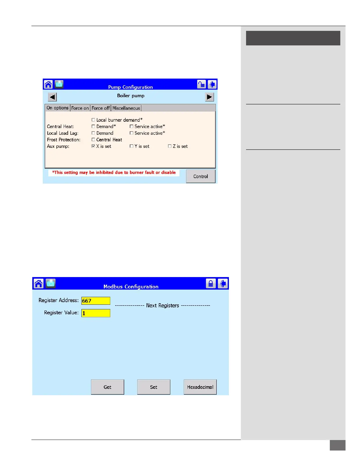
Next tap the advanced box in the bottom right hand corner of the pump
conguration screen. You should now see the screen displayed in Figure 72
below. Check the box “X is set” in the Aux pump row. This should be the only
checked box. These conguration steps must be completed on all boilers on the
lead/lag network.
Enabling Burner Fire Rate Output
This signal may be wired to a VFD or ECM (not supplied) dedicated boiler pump
to vary ow with ring rate. To enable the burner re rate output, start from the
SOLA home screen and select setup, control setup, then Modbus conguration.
See Figure 73 for the screen that will be displayed. Set the Register Address to
667. To enable a 4-20 mA output, set the Register Value to 1, or for a 0-10 VDC
output set the Register Value to 2.
FIGURE 72 ADVANCED PUMP CONFIGURATION SCREEN
FIGURE 73 ENABLING BURNER FIRE RATE OUTPUT
 Loading...