© The Fulton Companies 2016
INSTALLATION VTG-IOM-2016-1214 SECTION 2
2-4
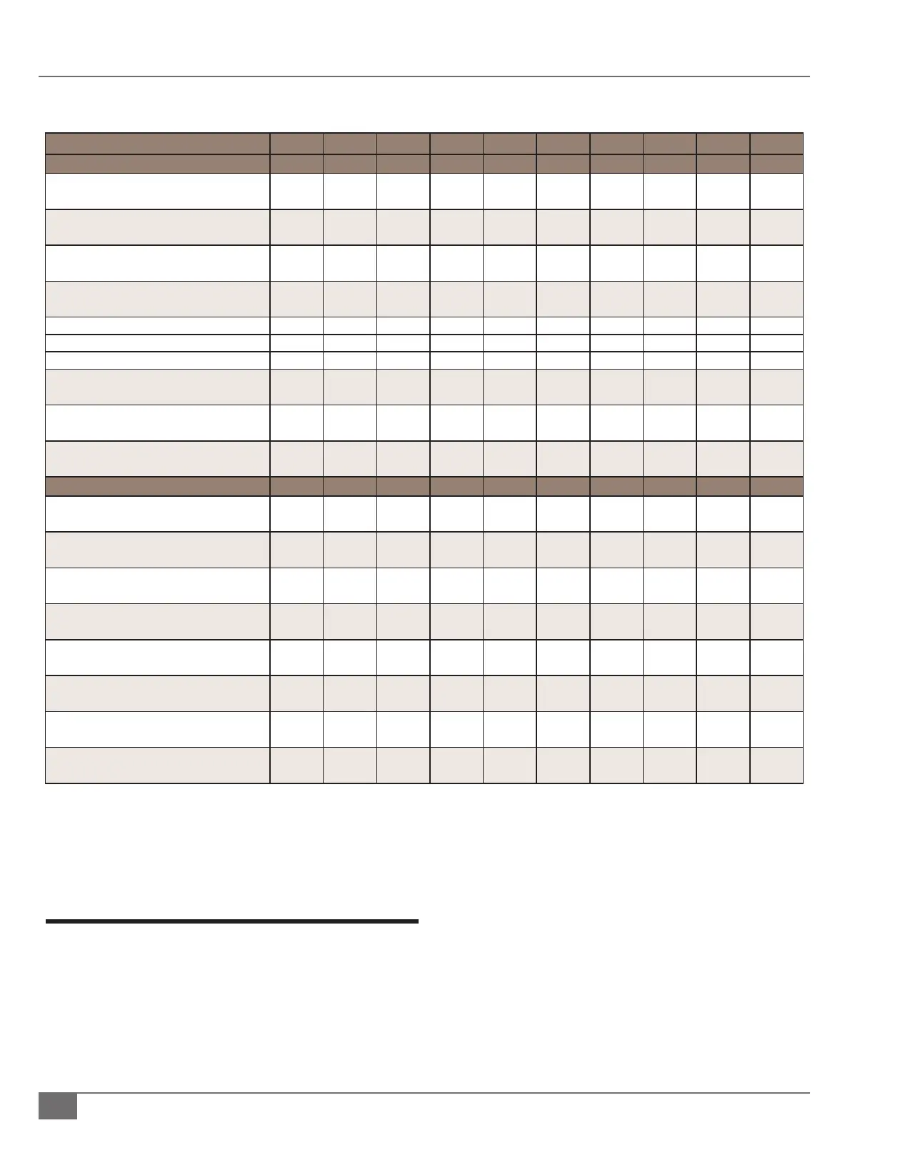
TABLE 1 BOILER DIMENSIONS AND OPERATING REQUIREMENTS
MODEL VTG
2000 2000DF 3000 3000DF 4000 4000DF 5000 5000DF 6000 6000DF
Specications
Input Million BTU/Hr.
kW
2
586
2
586
3
879
3
879
4
1172
4
1172
5
1465
5
1465
6
1758
6
1758
Fuel Cons. @ rated cap: (Nat. Gas) FT3/Hr.
M
3/Hr
2,000
56.6
2,000
56.6
3,000
84.9
3,000
84.9
4,000
113.2
4,000
113.2
5,000
141.5
5,000
134.5
6,000
169.9
6,000
169.9
Fuel Cons. @ rated cap.: (#2 Oil) GPH
LPH
NA
NA
14.3
54.1
NA
NA
21.4
81.0
NA
NA
28.6
108.2
NA
NA
35.8
135.5
NA
NA
42.8
162.0
Output at AHRI Test Condition BHP
KCal/h
57
4.8
57
4.8
86
7.25
86
7.25
116
9.7
116
9.7
138
11.6
138
11.6
168
14.1
168
14.1
Electrical Req. (FLA) 208V, 60Hz, 3 Phase
13 16 16 19 22 19 29 34 29 34
230V, 60Hz, 3 Phase
10 14 14 16 19 16 26 30 26 30
460V, 60Hz, 3 Phase
5 7 7 8 10 8 13 15 13 15
Water Content Gal
Liters
147
556.4
147
556.4
215
813.8
215
813.8
275
1041
275
1041
275
1041
275
1041
480
1817
480
1817
Dry Weight LB
KG
3,800
1724
3,800
1724
5,300
2404
5,300
2404
6,600
2994
6,600
2994
6,900
3130
6,900
3130
10,800
4899
10,900
4944
Operating Weight LB
KG
5,100
2314
5,100
2314
7,100
3221
7,100
3221
8,900
4037
8,900
4037
9,200
4173
9,200
4173
14,800
6713
14,900
6759
Dimensions
A. Boiler Width IN
CM
30.5
77.5
30.5
77.5
34.5
87.6
34.5
87.6
40.5
102.8
40.5
102.8
40.5
102.8
40.5
102.8
50.5
128.2
50.5
128.2
B. Overall Boiler Height IN
CM
75.6
192.0
64
162.5
90.4
229.6
72.3
183.6
92
233.6
77.9
197.8
98.7
250.6
77.9
197.8
88.2
224.0
88.2
224.0
C. Overall Boiler Depth IN
CM
108
274.3
122
309.8
120
304.8
132
335.2
124
314.9
136
345.4
136
345.4
142
360.6
155
393.7
155
393.7
D. Flue Outlet Diameter IN
CM
10
25.4
10
25.4
12
30.4
12
30.4
14
35.5
14
35.5
14
35.5
14
35.5
14
35.5
14
35.5
E. Air Inlet Diameter IN
CM
8
20.3
10
25.4
10
25.4
10
25.4
12
30.4
12
30.4
12
30.4
12
30.4
12
30.4
12
30.4
F. Water Inlet/Outlet Diameter IN
CM
4
10.1
4
10.1
4
10.1
4
10.1
6
15.2
6
15.2
6
15.2
6
15.2
6
15.2
6
15.2
G. Min. Clearance to Ceiling IN
CM
24
60.9
24
60.9
24
60.9
24
60.9
24
60.9
24
60.9
24
60.9
24
60.9
24
60.9
24
60.9
H. Overall Height (w/o blower) IN
CM
60.9
154.6
68.1
172.9
72.3
183.6
72.3
183.6
77.9
197.8
77.9
197.8
77.9
197.8
77.9
197.8
88.2
224.0
88.2
224.0
Clearances and Serviceability
Adhere to the following for clearances and serviceability:
1. All local and national codes (NFPA, ANSI, UL, CSA,
ASME) must be followed for proper clearances and
serviceability for your boiler or heater. Authorities
having jurisdiction should be consulted before
installations are made.
2. Appropriate front, back, side and top clearances must
be maintained (Figure 1). This will allow access around
the equipment to facilitate maintenance and a safe
work environment. A 1 inch (25.4 mm) side clearance
is acceptable between all boilers, with the exception of
the VTG-5000 which requires an 8 inch (203.2 mm) side
clearance. Custom congurations may not allow 1 inch
(25.4 mm) side clearance.
* Alternate gas pressure arrangements may apply. Please verify gas pressure ratings for your boiler by viewing the boiler name plate.
** Typical 120 VAC controls allow for a +10% and a -15% voltage uctuation.
***Standard congurations. Alternate voltages available as an option; please consult factory.
Note: All dimensions are approximate and are subject to change without notice.
The use of propane may be allowable with concentrations up to 5% propylene, also referred to as HD5. O-standard grades of propane are not permitted. Contact
factory for more information.
 Loading...


