EasyManua.ls Logo

FUNAI LT6-M19BB User Manual

FUNAI LT6-M19BB
62 pages
To Next Page IconTo Next Page
Page #1 background imageLoading...
Page #1 background image
SERVICE MANUAL
This Service Manual is for the
LT6-M19BB(A8CN1EP)
/LT6-M19WB(A8CN4EP) model.
For the LT6-M19BB(A8CN1EP)
/LT6-M19WB(A8CN4EP) model,
the letter (A8CN1EP)/(A8CN4EP) is
printed on the Serial No. Label.
Refer to the Serial No. Label on the
right.
Serial No. Label
"A8CN1EP"
Serial No. Label
"A8CN4EP"
19 COLOR LCD TELEVISION
LT6-M19BB/LT6-M19WB
Question and Answer IconNeed help?

Do you have a question about the FUNAI LT6-M19BB and is the answer not in the manual?

FUNAI LT6-M19BB Specifications

General IconGeneral
Screen Size19 inches
Resolution1366 x 768
Display TypeLCD
HDMI Ports1
USB Ports1
Weight2.7 kg (with stand)
Aspect Ratio16:9
Contrast Ratio1000:1
Brightness250 cd/m²
Response Time5 ms
Speakers2 x 3W
Viewing Angle170° (H) / 160° (V)
InputsHDMI, USB, VGA, Composite

Summary

FUNAI Service Manual

Product Identification and Model Details

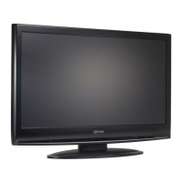
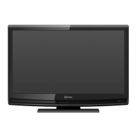
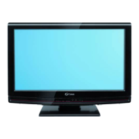
Identifies models LT6-M19BB/LT6-M19WB and serial number label.

19" Color LCD Television Overview

Main product title and model information.

Television Specifications

Tuner and LCD Panel Specs

Tuner input, IF, LCD pixels, and viewing angle specifications.

DVB-T and Video Specs

DVB-T reception, video settings like overscan, brightness, resolution.

Audio Performance Specifications

Audio Output Power and Distortion

Specifies audio output power, distortion, and frequency response.

Audio Signal-to-Noise Ratio

Specifies audio S/N ratio for video and component inputs.

Important Safety Precautions

Pre-Service Safety Checks

General safety checks before returning instrument to customer.

Antenna and Leakage Current Safety Tests

Procedures for checking antenna input and leakage current.

Warning Against Design Alterations

Warns against altering the product's design due to safety hazards.

Servicing Safety: Hot Chassis and Precautions

Hot Chassis Grounding and Servicing

Explains hot chassis ground and safety servicing requirements.

Lead Dress and Product Safety Notices

Emphasizes lead dress, safety parts, and correct replacements.

Servicing Precautions and Guidelines

Part Replacement and Radiation Safety

Notes parts identified by 'A' symbol and regulations for spurious radiation.

Wiring, Insulation, and Component Handling

Specifies wiring, insulation, soldering, and foreign object rules.

Post-Servicing Safety Checks

Clearance Distance Verification

Confirms clearance distance between terminals and metallic parts.

Leakage Current Test Procedure

Details on measuring leakage current using load Z and AC voltmeter.

Servicing Standards and Notes

Circuit Board Pin Identification

Explains how to identify pins on ICs and connectors.

Solder Usage Guidelines

Guidance on using Pb-free solder based on PCB markings.

Flat Pack-IC Removal and Installation

Step-by-step instructions for removing and installing flat pack ICs.

Flat Pack-IC Removal Methods

IC Removal using Soldering Iron

Method for removing flat pack ICs using a soldering iron and desoldering braid.

IC Removal using Iron Wire

Method for removing flat pack ICs using iron wire and hot air blower.

Flat Pack-IC Installation and ESD Protection

Flat Pack-IC Installation Procedure

Steps for installing a flat pack IC, including pin alignment and soldering.

Semiconductor Handling and ESD Prevention

Guidance on grounding human body and workbench to prevent ESD.

Cabinet Disassembly Instructions

Disassembly Flowchart and Methods

Flowchart illustrating cabinet disassembly steps and part removal notation.

Electrical Adjustment Procedures

Required Test Equipment for Adjustments

Lists necessary test equipment for electrical adjustments.

Service Mode Entry Procedure

Steps to enter the service mode using the remote control.

Service Remote Control Creation

Instructions for creating a service remote control unit.

Service Mode Adjustments: Purity and VCOM

Purity Check Mode Operation

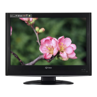
Cycles through colors to check for non-active pixels.

VCOM Adjustment Procedure

Procedure for adjusting VCOM using a color analyzer.

Advanced LCD Calibration

White Balance Adjustment

Adjusts red, green, and blue beams for pure white balance.

Color Temperature Adjustments (Cutoff/Drive)

Adjusts cutoff and drive for color temperature and values.

LCD Television Initialization Procedure

TV Initialization Process

Steps to initialize the LCD television via the service remote control.

System Control Block Diagram

Video Signal Block Diagram

Audio-1 Signal Block Diagram

Audio-2 Signal Block Diagram

Digital Signal Processing Block Diagram

Inverter Circuit Block Diagram

Power Supply Block Diagram

Schematic Diagrams and Test Points

Schematic Diagram Standard Notes

Notes on component identification, ordering, and values.

Schematic Diagram Warnings

Emphasizes special part characteristics and safety hazards from substitutes.

Schematic Diagram Conventions

Caution, Notes, and Symbol Guide

Explains cautions, notes, and symbols used in schematics.

Voltage and Line Reading Guides

Illustrates voltage indications and line references.

Test Point Symbol Information

Symbols used to indicate test points on PCBs.

Main CBA Schematic Diagram (1/3)

Main CBA Schematic Diagram (2/3)

Main CBA Schematic Diagram (3/3)

Inverter & Junction Schematic Diagram

Function CBA Schematic Diagram

IR Sensor CBA Schematic Diagram

Digital Main CBA Diagram (1/6)

Digital Main CBA Diagram (2/6)

Digital Main CBA Diagram (3/6)

Digital Main CBA Diagram (4/6)

Digital Main CBA Diagram (5/6)

Digital Main CBA Diagram (6/6)

CBA Board Component Views

Main CBA Top and Bottom Views

Shows the top and bottom layout of components on the Main CBA board.

Inverter CBA Component Views

Inverter CBA Top View

Shows the top layout of components on the Inverter CBA board.

Inverter CBA Component Views (Cont.)

Inverter CBA Bottom View

Shows the bottom layout of components on the Inverter CBA board.

Specific CBA Board Component Views

Function CBA Top and Bottom Views

Shows the top and bottom views of the Function CBA board.

IR Sensor CBA Top and Bottom Views

Shows the top and bottom views of the IR Sensor CBA board.

CBA Board Component Views (Continued)

Jack CBA Top and Bottom Views

Shows the top and bottom views of the Jack CBA board.

Junction CBA Top and Bottom Views

Shows top and bottom views of the Junction CBA board.

Waveform Analysis for Servicing

Audio Waveform (WF1)

Oscilloscope waveform for audio signal at IC801 pin 14.

S-Video Waveforms (WF2, WF3)

Oscilloscope waveforms for S-VIDEO-Y and S-VIDEO-C.

Video Signal Waveforms (WF4-WF7)

Oscilloscope waveforms for VIDEO signals.

Wiring Diagrams

Exploded View of Cabinet Assembly

Product Packing Instructions

Mechanical Parts List

Product Safety Note for Parts

Safety note regarding parts with special characteristics.

Model and Mark Comparison Chart

Compares models LT6-M19BB/LT6-M19WB with their respective marks.

Mechanical Parts Breakdown Listing

Lists mechanical parts with reference numbers, descriptions, and part numbers.

Electrical Parts List

Safety Note and Component Tolerances

Safety note and tolerance symbols for capacitors/resistors.

Model and Mark Comparison

Compares models LT6-M19BB/LT6-M19WB with their respective marks.

CBA Unit Parts Lists

Lists parts for Digital Main, MMA, and Main CBA units.

Main CBA Component Lists (Capacitors, Diodes, Resistors)

Main CBA Capacitors

Lists capacitors for the Main CBA.

Main CBA Diodes

Lists diodes for the Main CBA.

Main CBA Resistors (C102-C519)

Lists resistors for the Main CBA.

Main CBA Diodes, ICs, and Coils

Main CBA Diodes (D802A-D990A)

Lists diodes with part numbers.

Main CBA Integrated Circuits (ICs)

Lists integrated circuits with part numbers.

Main CBA Coils

Lists coils used in the Main CBA.

Main CBA Transistors and Resistors (R102-R942)

Main CBA Transistors

Lists transistors used in the Main CBA.

Main CBA Resistors (R102-R942)

Lists resistors with part numbers.

Resistor Parts List (R621-R944)

Resistors (R621-R944)

Lists resistors with part numbers.

Resistor Parts List (R817-R944)

Resistors (R817-R944)

Lists resistors with part numbers.

Resistor and Miscellaneous Parts Lists

Resistors (R945-R999)

Lists resistors with part numbers.

Miscellaneous Components (AC Cords, Heat Sinks, Fuses)

Lists miscellaneous components like AC cords, heat sinks, fuses.

IR Sensor CBA Parts List

IR Sensor CBA Capacitors and Diodes

Lists capacitors and diodes for the IR Sensor CBA.

Function, Jack, and MUT CBA Parts Lists

Function CBA Parts List

Lists capacitors, connectors, diodes, resistors, and switches for Function CBA.

Jack CBA Parts List

Lists capacitors, connectors, resistors, switches, and miscellaneous for Jack CBA.

MUT CBA Components

Lists boards that constitute the MUT CBA.

Inverter CBA Parts List

Resistor and Junction CBA Parts Lists

Resistors (R401-R447)

Lists resistors with part numbers.

Resistors (R454-R457)

Lists resistors with part numbers.

Junction CBA Parts List

Lists connectors and miscellaneous parts for the Junction CBA.

Tuner Unit Identification

Identifies the tuner unit model.

Related product manuals