14
|
15
the 14-pin plug) should be connected to „Phone Out“, and the purple lead (pin 7 of the 14-pin plug) to „Phone In +“ of the Mini-ISO
socket.
For information on the phone connection options of your car audio system, please consult the manufacturer‘s user manual.
NOTE: If your car audio system has different phone connection options from those mentioned here, please consult a qualified pro-
fessional for installation of the system. Furthermore, please read the section with information on connecting the mute lead of the
ISO connection cable, “6.5.1 Checking the mute input”.
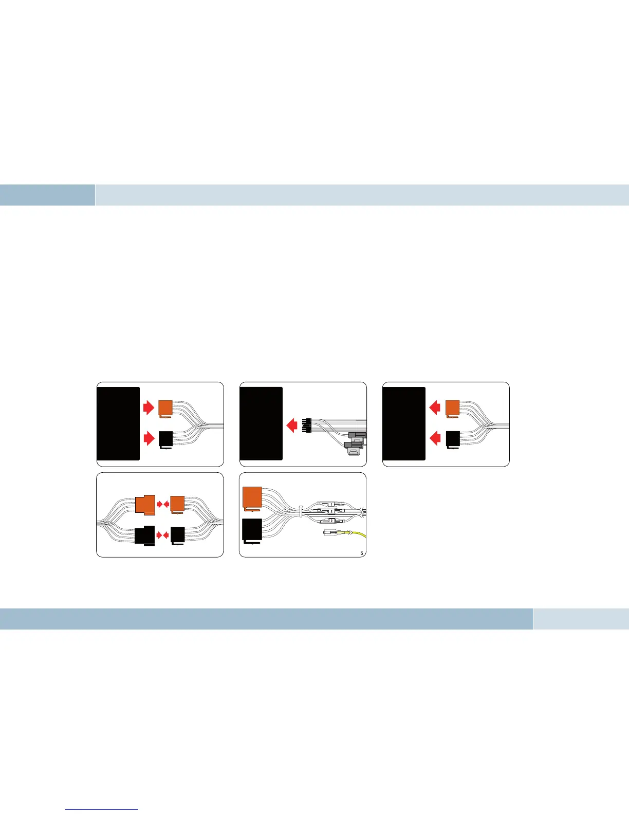
6.5 Installation of the ISO connecting cable
The battery must be disconnected before starting cable installation. Disconnect the grounding cable from the negative pole of the
battery. The cable installation procedure is shown in the illustrations.
When the installation is completed,
reconnect the grounding cable to the
negative pole of the battery.
Fig. 07:
Installation
procedure
Connect 14-pin ISO
connecting cable to
EGO FLASH
Disconnect car wiring
harness from car radio
Connect EGO FLASH ISO
connector to car radio
Connect EGO FLASH ISO connectors to car
wiring harness ISO connectors
Connect yellow mute lead to
one of the three mute inputs
(see table)
Car audio
Car audio
Electronics box
 Loading...