6.5.1 Checking the mute inputs
Picture 5 of Fig. 07 shows mute inputs 1–3. The yellow mute lead of the hands-free system should be connected to one of these
inputs. Which mute input should be selected is shown in the tables:
Fig. 08:
Type-dependent
pin allocation
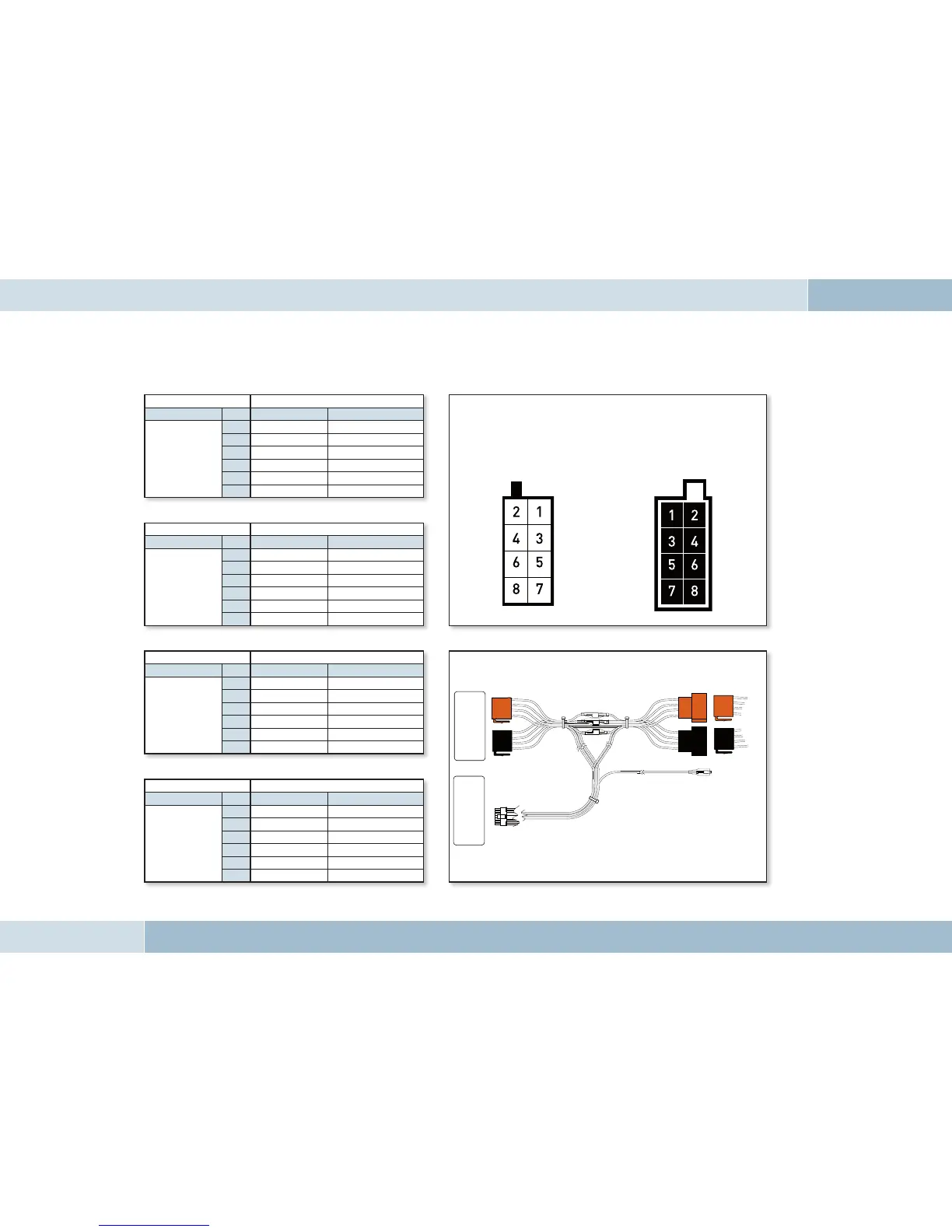
Fig. 10:
Connection system
Fig. 09:
Plug wiring scheme
Socket contact housing
Wiring of power supply connectors
Radio model Pin Wire colour Function
Audi,
Volkswagen,
Grundig
1
2
Mute
3
4
blue Ignition (15)
7
red Permanent positive (30)
8
brown Ground (31)
Socket contact housing
Radio model Pin Wire colour Function
Ford,
Mercedes,
Porsche,
Becker
1
2
3
Mute
4
red Permanent positive (30)
7
blue Ignition (15)
8
brown Ground (31)
Socket contact housing
Radio model Pin Wire colour Function
Blaupunkt
1
2
Mute
3
4
red Permanent positive (30)
7
blue Ignition (15)
8
brown Ground (31)
Socket contact housing
Radio model Pin Wire colour Function
Philips
1
Mute
2
3
4
red Permanent positive (30)
7
blue Ignition (15)
8
brown Ground (31)
Socket wiring from
the rear (see table)
Plug wiring from
the rear
Car audio
Electronics box
Vehicle wiring harness
EGO FLASH
 Loading...