12
2. WIRING
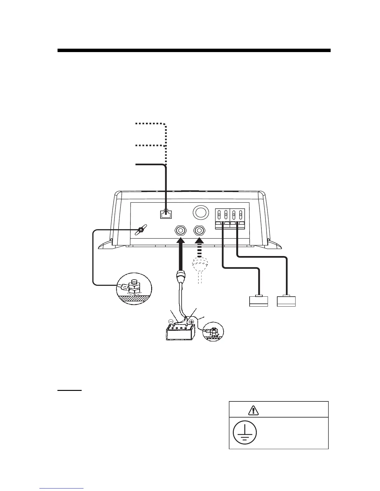
2.1 Wiring Outline
Connect the power cable, transducer cables, sensor cable, network cable and ground wire to their
respective locations on the network sounder. See the next page for how to connect the transducer
cables.
Ground
Connect a ground wire (IV-2 sq, local supply) between the
ground terminal and ship’s ground to prevent interference
to the sounder picture. Make the length of the wire as short
as possible. For FRP vessels, install a ground plate that
measures about 20 cm by 30 cm on the outside of the hull
bottom and connect the ground wire there.
GROUND
MOD-Z072-050+, 5 m
(option: 2/10 m)
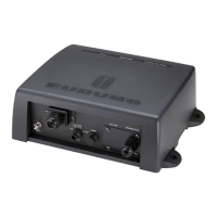
DFF3
Ground wire
(IV-2 sq)
BATTERY
White
Black
Shield (green)
12 - 24 VDC
MJ-A3SPF0013-035C
(3.5 m)
High Freq.
Transducer
Low Freq.
Transducer
HUB-101
NavNet,
NavNet vx2*
MJ-A6SPF0017
(option: 1/5/10/20/30 m)
Temperature or
Speed/Temperature
Sensor
NETWORK
12-24VDC
2.8-1.4A
TEMP
H TRANSDUCER L
MFD8/12/BB,
TZT9/14
MOD-WPAS0001-030+, 3 m
(for MFD8/12/BB /TZT9/14,
standard supply)
Model 17x2 Series, Model 17x2C Series, Model 17x4 Series, Model 17x4C Series,
GD-1720, GD-1720C, Model 18x3C(-BB) Series, Model 18x4C(-BB) Series,
Model 19x3C(-BB) Series, Model 19x4C(-BB) Series,GD-1900C(-BB), GD-1920C(-BB)
Ground the equipment
to prevent mutual
interference.
CAUTION