2. WIRING
manual.
GPS Antenna
GPS-017S
OR
RG-10U/Y
RG-10U/Y
Attached to Distributor
(approx. 1 m)
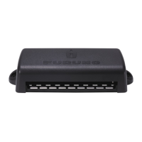
Distributor unit*
3
DB-1
12-24 VDC
(Connect to the
alternative power
source.)
100/110/115/200/
220/230 VAC
Power Supply
PR-240
DPYC-2.5
8D-FB-CV, (30 m/40 m/50 m, Option)
RG-10U/Y: Local supply
: Standard
: Option/local supply
DPYC-1.5*
2
0.2 m
*
1
*
1
*
1
0.8 m
Other external device
(See next page.)
Ground
IV-2.0sq
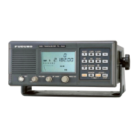
Transponder unit
FA-1701
Transponder unit
FA-1701
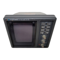
Monitor unit
FA-1702
IV-1.25sq
Z-AWG25X4P-SB *
5
IV-2.0sq
LAN*
4
*
1
: Connections must be waterproofed. See “How to secure and waterproof exposed connections” on page 2-3.
*
2
: DPYC-2.5, TTYCSLA-1, TTYCSLA-1Q, TTYCSLA-4 and TTYCSLA-7 are Japan Industry Standard cables.
Use them or the equivalents, referring to the "JIS CABLE GUIDE" on page AP-1.
*
3
: Ground is not required.
*
4
: When connecting the LAN cable, leave approx. 200 mm slack before clamping the cable at the cable clamps.
*
5
: Cable type varies depending on configuration. Z-AWG25X4P-SB cable may be substituted for TTYCSLA-4
type cable or locally supplied cable.
Transponder Unit 12-24 VDC, 6-3 A
Power supply specifications
12 VDC, 0.3 A max.
Monitor Unit
100-115/200-230 VAC, 1 phase, 50/60 HzAC/DC Power Supply Unit
GPS/VHF
combined antenna
GVA-100-T
VHF antenna
VHF antenna

 Loading...