1. MOUNTING
1-5
1.1.3 GPS/VHF combined antenna (GVA-100-T)
Install the combined antenna unit referring to the outline drawing. When selecting a
mounting location for the antenna, keep in mind the following points.
• Select a location out of the radar beam. The radar beam will obstruct or prevent re-
ception of the GPS satellite signal.
• There should be no interfering object within the line-of-sight to the satellites. Objects
within line-of-sight to a satellite, for example, a mast, may block reception or prolong
acquisition time.
• Mount the antenna unit as high as possible. Mounting it this way keeps it free of in-
terfering objects and water spray, which can interrupt reception of GPS satellite sig-
nal if the water freezes.
• Also, refer to the antenna installation guidelines on page 1-3.
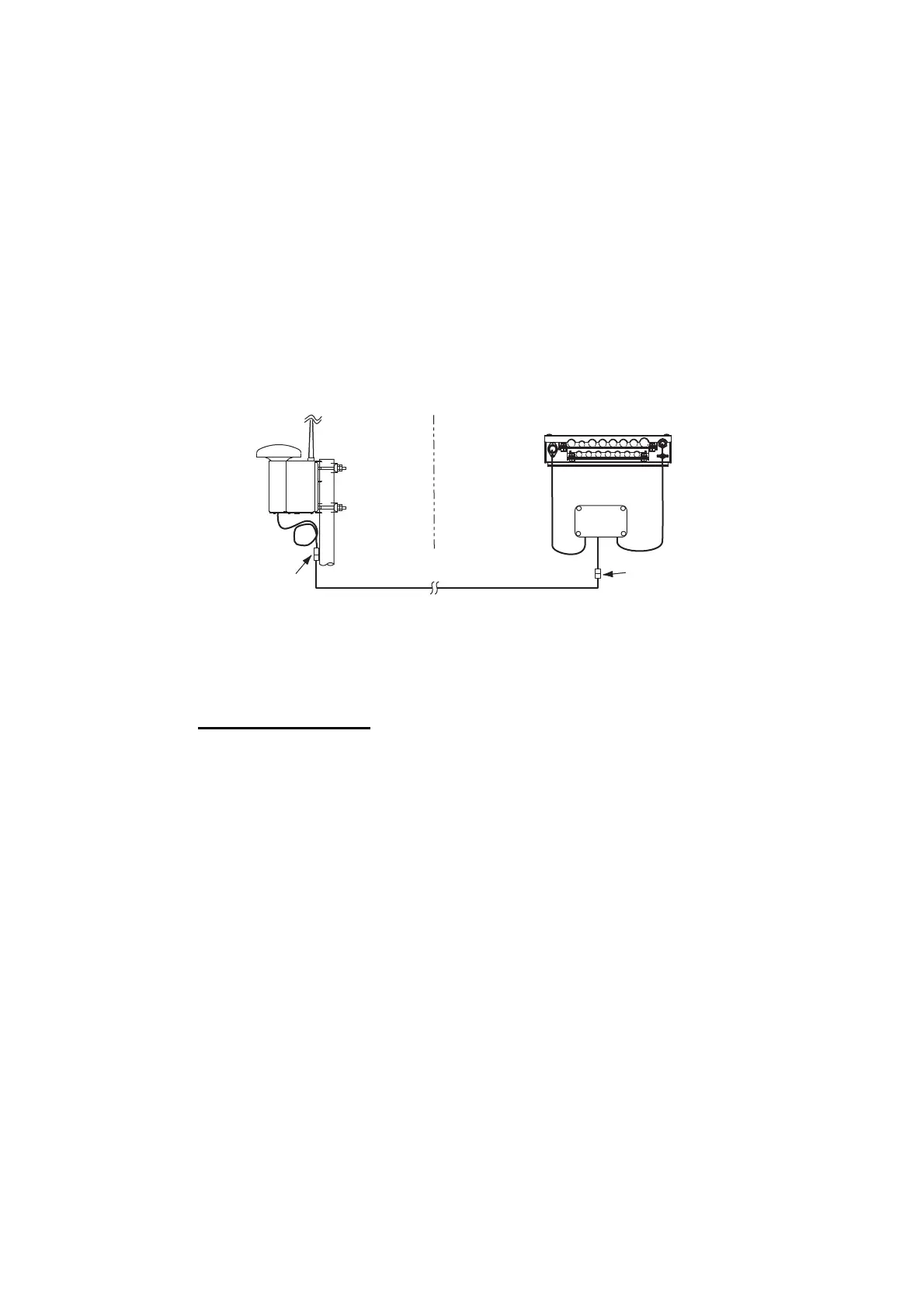
Installation overview of GPS/VHF combined antenna
Note: Where the mast on which the antenna is installed has a diameter of 60 mm to
80 mm, the optional mast installation kit is required (Model: OP24-5, Code: 005-954-
510).
Mounting procedure
1. Dismount the bottom cover, cut the cable-tie inside the unit and take out the co-
axial connector attached to the combined box.
2. Loosen four screws to loosen whip antenna fixture and pull out the coaxial con-
nector coming from the combined box through the hole in the whip antenna fixture.
3. Connect the coaxial connector to the whip antenna base and wrap the junction
part of the whip antenna with vulcanizing tape and then vinyl tape for waterproof-
ing.
4. Insert the whip antenna from the top of the combined antenna.
5. Secure the whip antenna with whip antenna fixture.
6. Using a new cable tie (supplied), secure the cables and coaxial connector inside
the antenna case.
7. Mount the bottom cover.
8. Fix the GPS/VHF combined antenna to the ship’s stanchion (40 to 50 mm diame-
ter) with antenna fixing brackets, flat washers and hex nuts.
Outdoor
Indoor
N-P-8DFB
N-P-8DFB
Distributor
DB-1
GPS
AIS Transponder
VHF
RG-10U/Y

 Loading...