1. MOUNTING
1-4
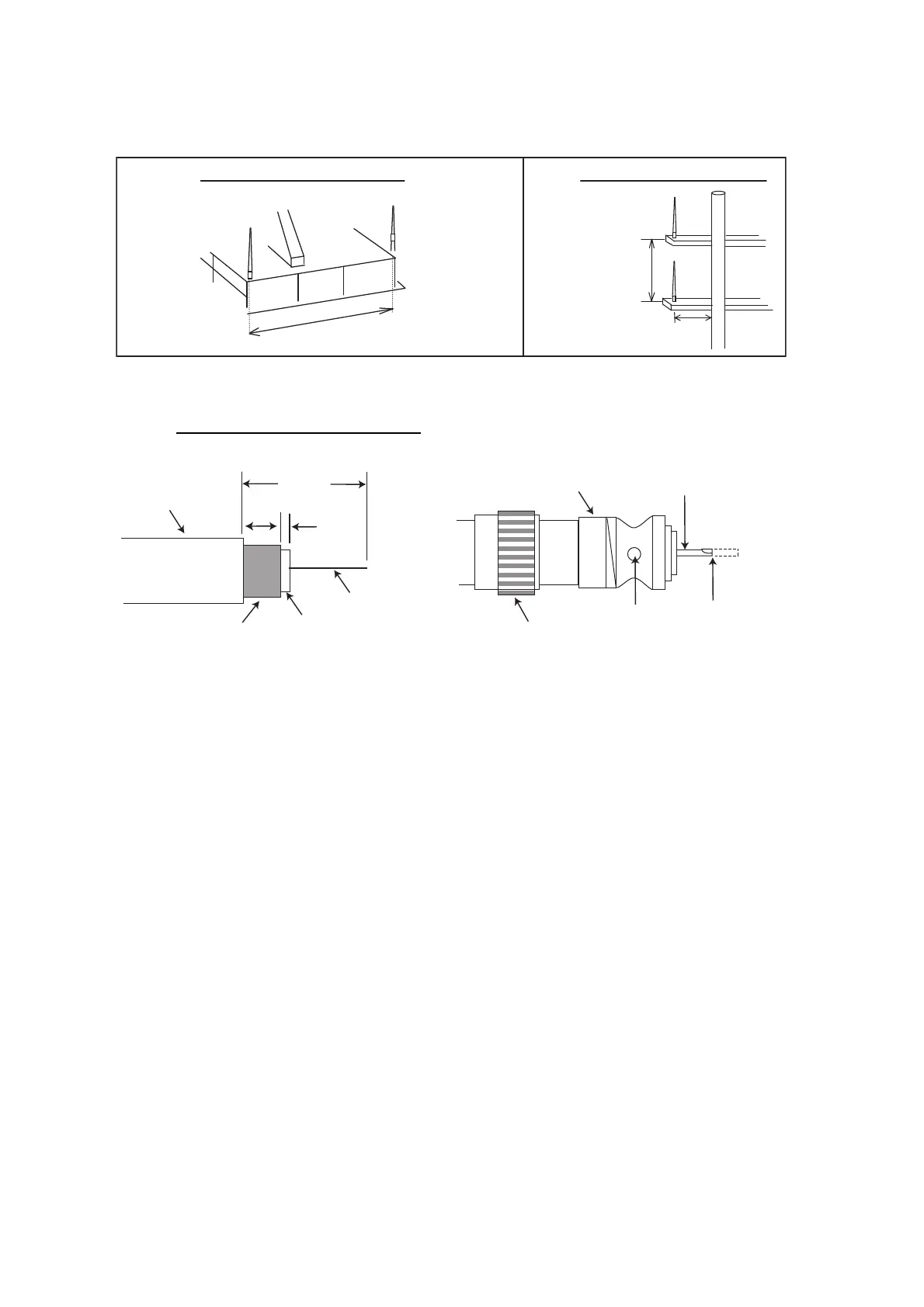
• Install the VHF whip antenna referring to the outline drawing at the back of this man-
ual. Separate this antenna from other VHF radiotelephone antennas as shown be-
low to prevent interference to the FA-170.
When coaxial cable RG-10/UY (shipyard supply) is used, attach the coaxial plug
M-P-7 (dockyard supply) as shown on the following page.
How to attach the plug M-P-7
Lay the coaxial cable and attach an M-type plug (if necessary) to the cable as follows.
1. Remove the sheath by 30 mm.
2. Bare 23 mm of the center conductor. Trim braided shield by 5 mm and tin.
3. Slide coupling ring onto cable.
4. Screw the plug assembly on the cable.
5. Solder plug assembly to braided shield through solder holes. Solder contact
sleeve to conductor.
6. Screw coupling ring into plug assembly.
More than 10 m
Other VHF whip
antenna
Whip antenna for AIS
(GPS/VHF combined
antenna)
More than
0.5 m
More than
2.8 m
Horizontal separation distance Vertical separation distance
Sheath
30 mm
5 mm
2 mm
Conductor
Insulator
Braided shield
Plug assembly
Contact sleeve
Cut conductor
here.
Solder both
sides of hole.
Coupling ring

 Loading...