2. WIRING
2-7
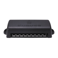
2.3.3 How to connect the FA-1703 (Pilot Plug Unit, optional)
The FA-1703 is shipped with a flushmount panel attached. The flushmount panel can
be removed if it is not required.
The example figures below show the FA-1703 without a flushmount panel.
1. Unfasten the four screws at the locations indicated with arrows in the figure below.
2. Remove the rear cover of the FA-1703. The 05P0895 board, with three SATO
PARTS connectors, is exposed.
3. Referring to "Unit Interconnection" on page 2-4 and the interconnection diagram
at the rear of this manual, connect the FA-1703.
4. Pass the connected cables through the locking wire saddle on the rear cover, then
fit the rear cover to the FA-1703.
5. Fasten the four screws removed at step 1, then secure the connected cables to
the cable clamp with cable ties.
DISP1 DISP2
05P0895 board
COM
Locking wire saddles
Cable clamp
Rear cover
Rear coverRear cover
Cable
ties
Cable
ties

 Loading...