1. MOUNTING
1-2
c) Cable type RG-10/UY (shipyard supply)
Note: The length of this cable should be less than 20 m to prevent signal loss. The
coax. coupling cable assy. (type: NJ-TP+3DXV-1, code no. 000-123-809-10), co-
axial connector (N-P-8DFB; supplied), vulcanizing tape and vinyl tape are re-
quired. Fabricate both ends of the cable as shown in the figure on the next page.
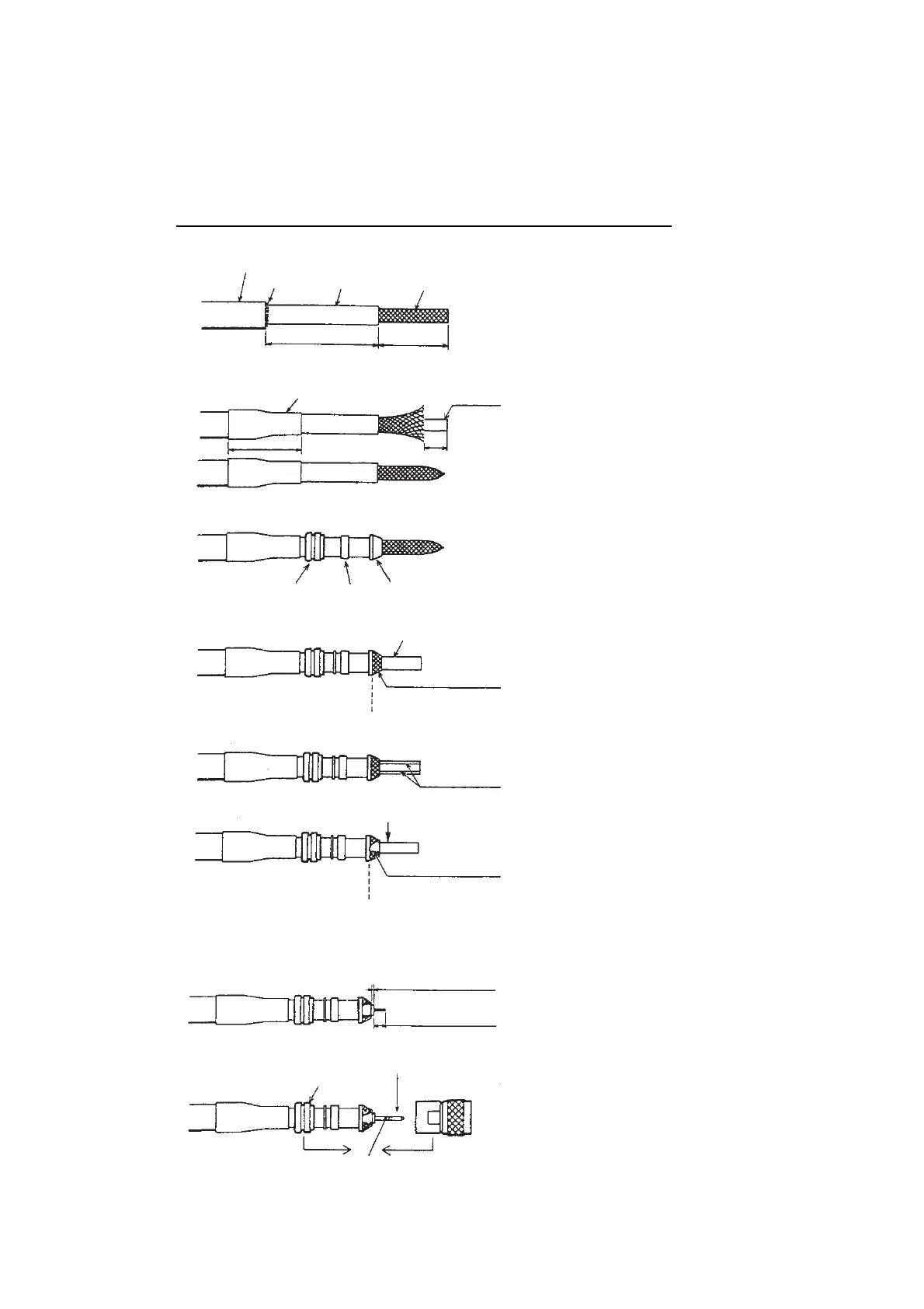
How to attach the connector N-P-8DFB for cable 8D-FB-CV
Outer Sheath
Armor
Dimensions in millimeters.
Inner Sheath Shield
Remove outer sheath and armor by the
dimensions shown left.
Expose inner sheath and shield by the
dimensions shown left.
Cut off insulator and core by 10 mm.
Twist shield end.
Slip on clamp nut, gasket and clamp as
shown left.
Fold back shield over clamp and trim.
Cut aluminum foil at four places, 90° from one
another.
Fold back aluminum foil onto shield and trim.
Expose the insulator by 1 mm.
Expose the core by 5 mm.
Slip the pin onto the conductor. Solder them
together through the hole on the pin.
Insert the pin into the shell. Screw the clamp
nut into the shell.
(Tighten by turning the clamp nut. Do not
tighten by turning the shell.)
Cover with heat-shrink tubing and heat.
30
10
Clamp
Nut
Gasket
(reddish
brown)
Clamp
Aluminum Foil
Trim shield here.
Trim aluminum
tape foil here.
Insulator
1
5
Clamp Nut
Pin
Shell
Solder through
the hole.
50
30

 Loading...