RADAR SENSOR
DRS2D/DRS4D
OR
RADAR SENSOR
DRS4A/DRS6A/DRS12A/DRS25A
CCD Camera
CCD Camera
FI-5002
SC-30
GP-330
FI-50, etc.
IF-NMEA2K1/2
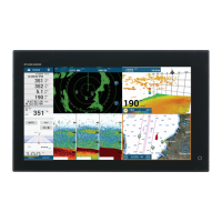
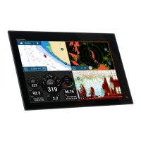
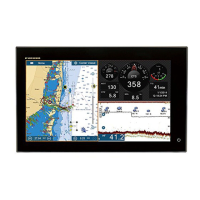
Multi Function
Display
TZT9/TZT14
12/24 VDC
: Standard Supply
Event SW
External Buzzer
Speed Alarm
Power input for CAN bus
IP Camera
Echo Sounder
(FCV-1150, BBDS1, DFF series)
Environmental category
Sensor units: Exposed to the weather
All other units: Protected from the weather
NAVpilot-700
12-24 VDC
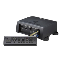
POWER SUPPLY UNIT*
PSU-017
*: The power supply unit is required when you connect the radar sensor.
PSU-012: w/DRS2D/4D/4A/6A/12A
PSU-013: w/DRS25A
PSU-017: w/DRS2D/4D
For details of the power supply unit, see the installation manual of the radar sensor (IME-35670).
HUB -101
FA-30/50
FAX-30
FUSION-Link Equipment
FAR-2xx7 series
Wide Monitor
Network Equipment
12-24 VDC
POWER SUPPLY UNIT*
PSU-012/PSU-013
MCU-002
 Loading...