• BEFORE USING
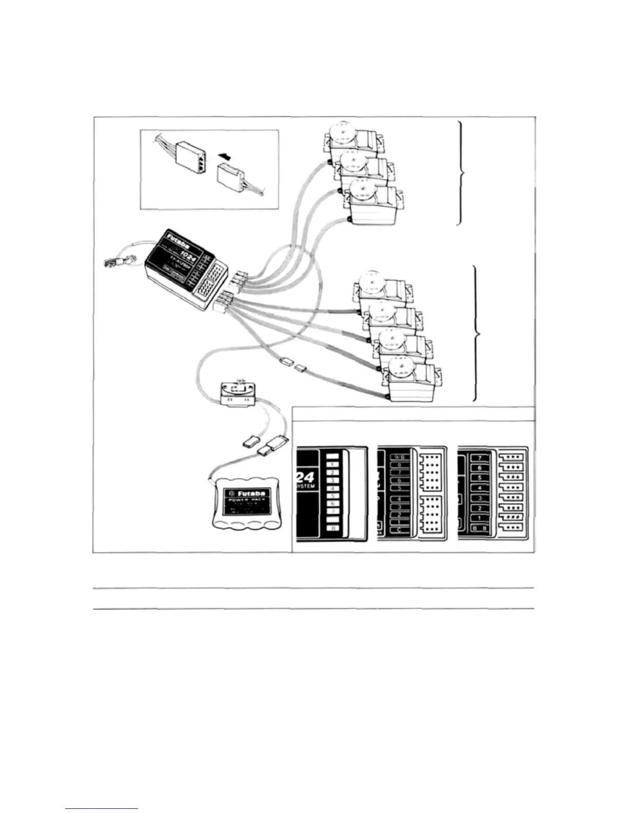
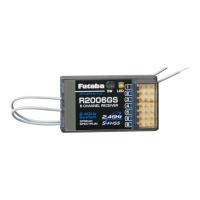
• RECEIVER AND SERVO CONNECTIONS
Pay careful attention to the
polarity of the connector.
CH7 (AUX)
CH6 Flap servo
CH5
Landing gear
servo
Option
(sold separately)
Antenna
wire
PCM receiver
FP-R129DP, FP-R137GPor
FM receiver FP-R-128DF
CH4
Rudder
servo
CH3
Throttle
servo
Four servos
are supplied
as standard.
CH2
Elevator
servo
CH1
Aileron
servo
Extension cord
Receiver switch
Charging jack
Receiver connector arrangement
FP-R137GP
FP-R129DP
FP-R128DF
Nicd battery pack
NR-4J
PRECAUTIONS
• Connect the receiver, servos, switches, and bat-
tery as shown in the figure. Extend the trans-
mitter and receiver antennas to their full
length.
•Turn
on the transmitter power
switch,
then
turn on the receiver power switch.
The
servos
will
go
to
their
neutral
position.
Move the transmitter sticks one at a time to
check that each servo follows its control stick
movement.
• Connect the pushrods to the servos and check
that the direction of travel of each servo
matches the direction of movement of its con-
trol
stick. If
a
servo
does
not
move
in the prop-
er direction, switch its direction with the servo
reversing function.
•
Operate
each
servo
horn
over its
full
stroke and
check that the pushrod does not bind or is not
too loose. Unreasonable force applied to the
servo
horn
will
adversely
affect the
servo
and
- 4 -