• BEFORE USING
drain the battery pack very quickly. Make the
travel of each control mechanism somewhat
larger than the full stroke (including trim) of
the servo horn. Adjust the servo horns so that
they move smoothly even when the trim lever
and stick are operated simultaneously in the
same direction.
• Be alert for noise.
This set is noise-resistant, but not completely
immune to noise. The use of noiseless parts is
recommended.
•When installing the switch harness, cut a rec-
tangular hole slightly larger than the full stroke
of the switch and install the switch so that it
moves smoothly from ON to OFF. Also do this
when the switch is installed inside the fuselage
and is turned on and off from the outside with
a piece of wire. Install the switch where it will
not be exposed to engine oil or dust and dirt.
• Although the antenna appears to be too long,
do not cut it or fold it back.
• Install the servos securely. Tighten the mount-
ing screws until the rubber damper is crushed
slightly. If the screws are too tight, the cushion-
ing effect will be adversely effected.
• The crystal can be changed from the outside of
the receiver case. Always use the Futaba trans-
mitter/receiver matched crystal set to change
the band.
• The receiver that is used with the 7UAP and
7UAF is a dual conversion receiver. This re-
ceivers requires a special crystal so please order
the correct crystal set.
• Spare servo horns are supplied. Use them as
needed.
• Use extension cords matched to the model.
• Wrap the receiver in sponge rubber. Place it
inside a waterproof plastic bag and secure the
end of the bag with a rubber band. Do the
same with the airborne battery pack.
• Use the rubber bands wrapped around the re-
ceiver to hold the servo and switch leads.
• After installation and checking are complete,
perform a range check by collapsing the trans-
mitter antenna and extending the receiver
antenna to its full length and operating the
transmitter from a distance of 20 to 30 meters
from the receiver. The servos should operate
normally at this distance.
• Differs with the weather and surroundings.
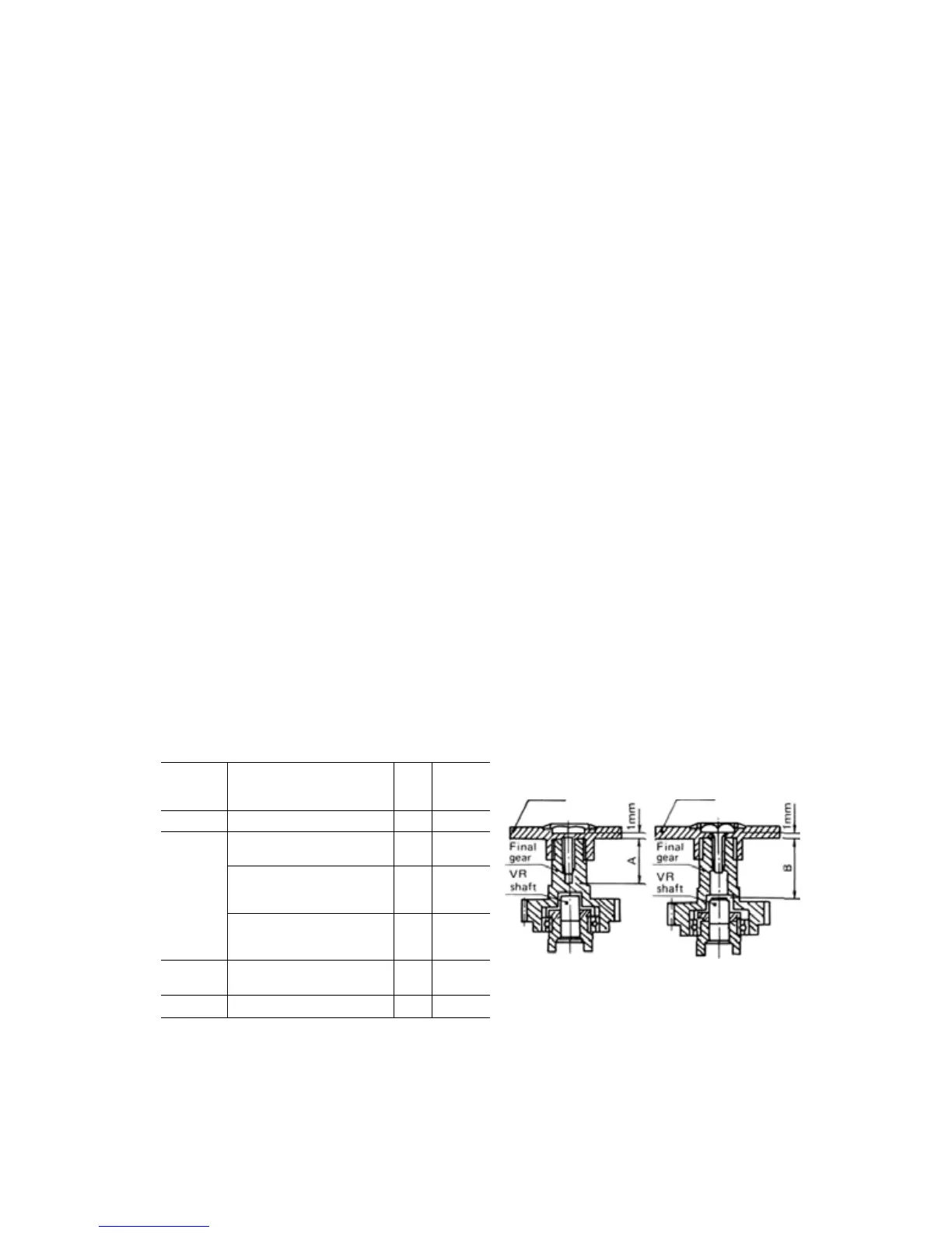
SERVO HORN MOUNTING SCREW PRECAUTIONS
Servo horn screws
Horn
mounting
screw size
2.6x6
2.6x8
2.6x10
2.6x12
Applicable servo
S133, S143 series
S 129 series
S130 series, S9101, S5101
S128 series
S132 series
S135 series, S9601
S136G
S138 series
S148 series
S131S series, S9201,S9301
89401
8134 series, 83301
Type
B
A
A
B
B
B
A
B
B
A
A
Dimen-
sions
(m/m)
5.7
7.9
7.9
11.9
7.3
8.7
9.0
9.9
10.5
9.0
11.3
Horn
Horn
Waterproof type A Non-waterproof type B
Notes
• The screws are 2.6m/m tapping screws.
• If screws longer than necessary are used, the final gear may be broken or the potentiometer may be damaged or
may fall out.
-5-