PIT Pitch
(Collective)
AUX1 Accessory 1
AUX2 Accessory 2
CH9 Channel 9
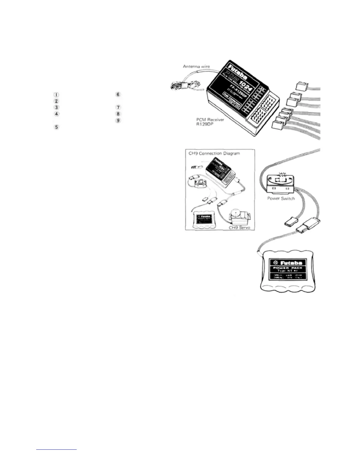
•RECEIVER AND
SERVOS
Receiver, servo, switch, and battery connections
The channel order is:
AIL Aileron
ELV Elevator
THR Throttle
RUD Rudder
(Tail rotor)
GER Retract gear
(Rate gyro
output
switching)
PRECAUTIONS
•Connect
the
receiver,
servos,
switch
harness,
etc. as shown in the figure. Extend the trans-
mitter and receiver antennas to their full
length. Turn on the transmitter power switch,
then turn on the receiver power switch. The
servos will go to their neutral position. Move
the transmitter sticks one at a time to check
that each servo follows its control stick move-
ment.
•Connect pushrods and linkages to the servos
and check that the direction of travel of each
servo matches the direction of movement of its
control stick. If a servo does not move in the
proper direction, use the servo reversing func-
tion
(See
page
14).
•
Operate
each
servo
to
its
full
extent,
and check
for binding and/or excess slop in the linkage or
pushrod. Unreasonable force on the servo arm
may damage
the
servo and
will
drain
the
bat-
teries very quickly.
• Adjust servo output arms and aircraft control
linkage as necessary so that each servo moves
smoothly throughout its full range of travel,
even when the control stick and trim lever are
operated simultaneously in the same direction.
•
Be
alert for possible sources of electrical noise.
This set is noise-resistant,
but the use of noise-
less
parts
is
recommended.
•When
installing
the
switch
harness,
make sure
that the switch can move smoothly, to its full
extent in each direction without binding.
Install the switch where it will not be exposed
to engine oil, dust, dirt, etc. The switch can be
installed inside the fuselage and operated from
the outside with a piece of wire.
•
Do NOT shorten the
receiver
antenna or
fold
it
back along its length.
•When installing the servos, tighten the mount-
ing screws so that the rubber grommets
are
compressed
slightly.
If
the
screws
are
too
tight,
the vibration-dampening
effect of the grommets
will be lost and servo
damage may occur.
• The crystal can be changed
without opening the receiver
case. Always use a Futaba
matched TX/RX crystal set
to change frequencies.
• Extra servo output arms are
supplied.Use them as needed.
• Use extension cords where necessary. RF
"chokes" are not required with the PCM
receiver.
• Wrap the receiver and the airborne battery
pack separately in foam padding. Padding
should be wrapped loosely for maximum vibra-
tion
protection.
Place
each
inside
a
waterproof
plastic bag and secure the end of the bag with a
rubber band.
• Use the rubber bands wrapped around the
receiver to hold the servo and switch leads.
•After installation and adjustments are com-
plete, perform a range check by collapsing the
transmitter antenna and extending the receiver
to its full length and operating the transmitter
from a distance of 60 to 90 feet from the
receiver (aircraft). The system should operate
normally at this range.
[4]