SENSOR BREAK DISPLAY
If a break is detected in the sensor circuit, the display will show:
SENSOR BREAK DISPLAY
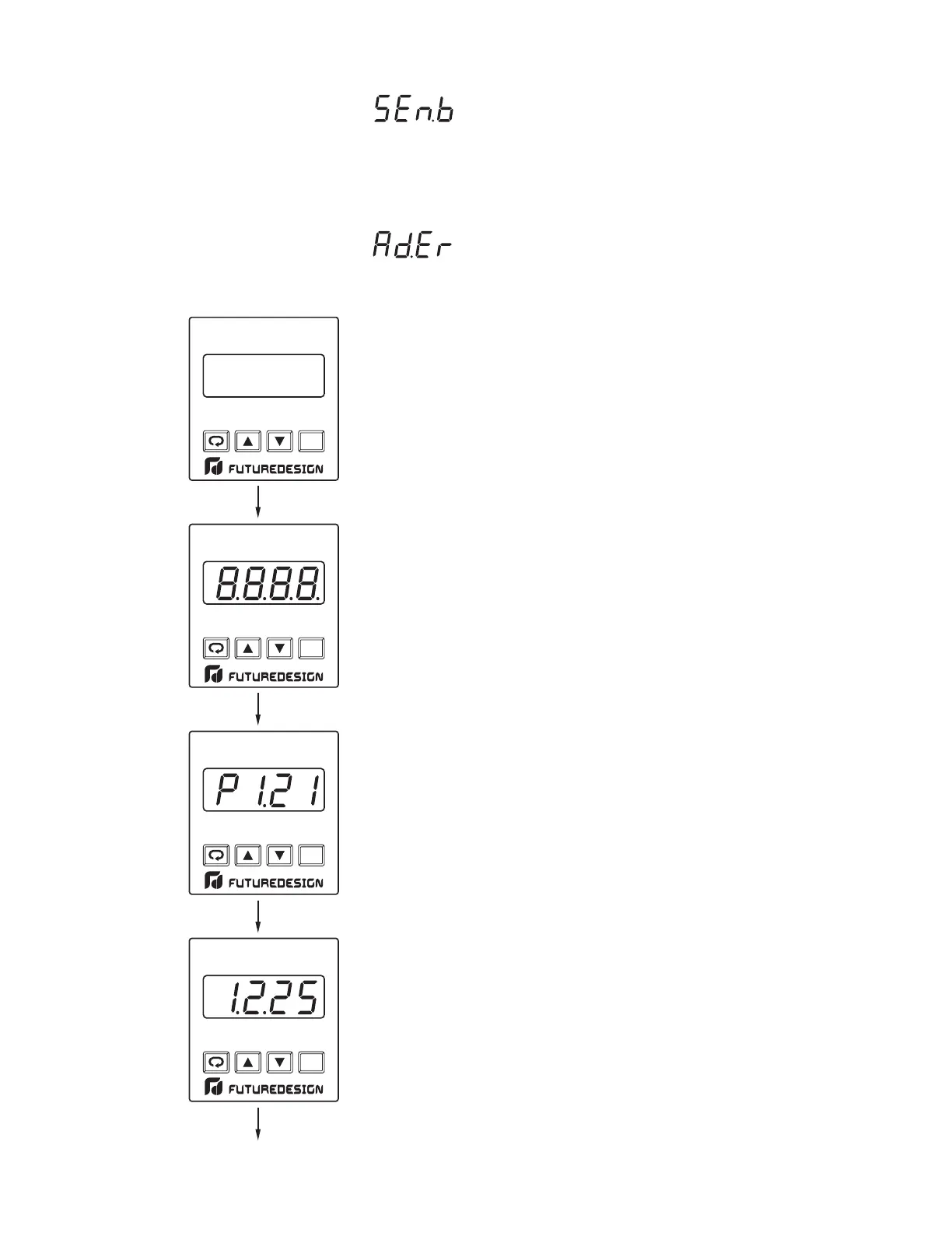
POWER UP SEQUENCEPOWER UP SEQUENCE
10
All segments of display and indicators are
left off for 0.5 second.
All segments of display and indicators are
lit for 1 second.
Display program code of the product for
1 second. The left diagram shows
program no.1 with version 21.
Display Date Code for 1 second. The left
diagram shows Year 2001, Month
February (2), Date 25'th. This means that
the product is produced on February
25'th, 2001. Note that the month code
is for is for and is
A
October, B November C
A
October,
B November C
A-D FAILURE DISPLAY
If failure is detected in the A-D converter circuit, the display will
show:
A-D FAILURE DISPLAY
LSP1
PV
OP1
HSP1
SP2
LOCK
RESET
OP2
FDC-L91LIMIT
LFLF
LCLC
LSP1
PV
OP1
HSP1
SP2
LOCK
RESET
OP2
FDC-L91LIMIT
LFLF
LCLC
LSP1
PV
OP1
HSP1
SP2
LOCK
RESET
OP2
FDC-L91LIMIT
LFLF
LCLC
RESET
FDC-L91LIMIT
UM L91-Rev 8