Step 2: Calibrate of A to D converter.
Send a span signal to terminal 4 and 5 with correct polarity.
The span signal is 60 mV for thermocouple input, 1V for
0-1V input, 10V for 0-10V input and 20mA for 0-20 mA input.
Press for at least 4 seconds. The display will blink a
moment. If the display didn't blink, then the calibration failed.
Gain
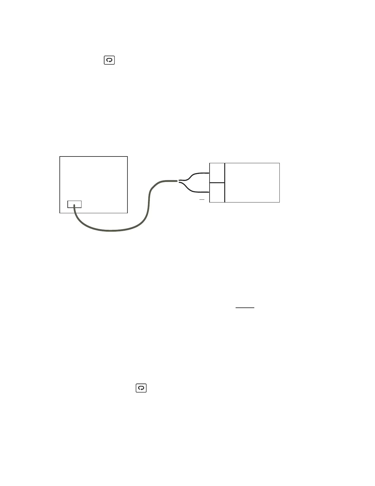
Step 3: Calibrate of .
Setup the equipment according to the following diagram
for calibrating the cold junction compensation. Note that a
K type thermocouple must be used.
offset cold junction
offset cold junction
4
5
Set the calibrator to be configured as K type thermocouple
output. Calibrator must have an internal compensation.
Send a 0.00 C signal to the unit under calibration.
Calibrator
K-TC
K+
K
NOTE: The unit under calibration is powered in a still-air room
at a temperature . Allow at least 20 minutes for
warming up.
25 +/-3 C
NOTE: The unit under calibration is powered in a still-air room
at
a temperature 25 +/-3 C. Allow at least 20 minutes for
warming
up.
Figure 5-2
Cold Junction
Calibration Setup
Figure 5-2
Cold Junction
Calibration
Setup
45
L91
Stay at least 20 minutes in still-
air room room temperature
25 +/- 3 C
UM L91-Rev 8
With CJTL on the display adjust the value to 0.00 reading.
Once adjusted, Press for at least 4 seconds. The display will
blink a moment. If the display didn't blink, then the calibration
failed.
The L91 being calibrated for Cold Junction Compensation MUST
be programmed for K t/c input, Celsius display to performing
the CJTL calibration.
prior