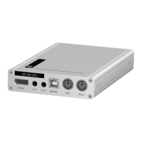
Console module »DVI-CON-MC2«
Computer and console modules · 105
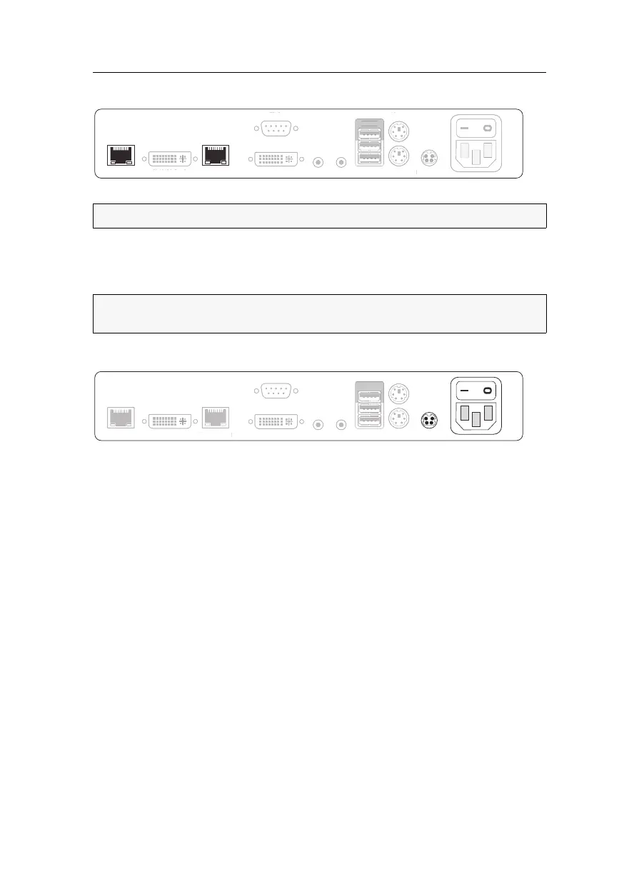
Connection to the matrix switch
Transmission 1: Connect this interface to a Dynamic Port (RJ45) of the matrix switch.
Transmission 2: Connect this interface to another Dynamic Port (RJ45) of the matrix
switch.
Power supply
Main Power: Connect the supplied power cable.
Insert the cable’s Schuko plug in a power socket.
Red. Power: Connect the connection cable of a compatible power pack to provide the
console module with a second, redundant power supply.
Startup
Turn on the console module after its installation.
Use the Main Power power pack or a redundant power pack to establish the power
supply:
Turn on the Main Power power pack.
Use an optional power pack to supply the Red. Power socket with power.
NOTE:
Use category 5e (or better) twisted pair cables to connect the devices.
NOTE:
You can also connect the console module directly to a compatible computer
module.
Main Power
LED Out
DVI/VGA Out 1
DVI/VGA Out 2
Red. Power
Mouse
Keyb.
Micro In
Speaker
Generic
Keyb./Mouse
Transmission 2
Transmission 1
DVI/V
A Out
n
ower
LED
ut
VI
V
A Out 1
Red. Power
ouse
eyb
i
r
I
S
eake
eneri
Keyb./Mous
Main Power
LED Out
DVI/VGA Out 1
DVI/VGA Out 2
Red. Power
Mouse
Keyb.
Micro In
Speaker
Generic
Keyb./Mouse
Transmission 2
Transmission 1
LED
ut
VI
V
A Out 1
DVI/V
A Out
ou
e
ey
r
eake
eneri
ey
.
ous
Transmission
Transmission