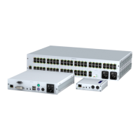
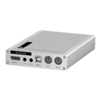
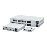
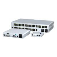
Computer module »VGA-CPU-UC«
90 · Computer and console modules
Trans. 1: Connect this interface to a Dynamic Port (RJ45) of the first matrix switch.
Trans. 2: Connect this interface to a Dynamic Port (RJ45) of the second matrix switch.
Power supply
Power In: : Insert the power pack’s connection cable to this interface. Then, connect
the power cable to the power pack and a power socket.
Status displays
The LED on the back panel of the computer module show the status of the external
power pack:
The blinking Transmission LEDs highlight the following operating statuses of the
particular connection:
ADVICE:
You can also connect the computer module directly to up to two compatible
console modules.
LED Status Meaning
Power On The external power pack is connected and the required voltage (12 Volt)
is available.
Off The external power pack is not (properly) connected.
LED Colour Status Meaning
Left Yellow Off No console module accesses the computer module.
On A console module accesses the computer module.
Blinking The incoming video signal was not detected.
Flashing No voltage at PS/2 interface or USB bus.
Right Green Off The computer module is turned off.
On A console module accesses the computer module.
Blinking The connection to the counterpart could not be established.
Flashing The connection to the counterpart is established.
No console module is accessing.
Flickering Keyboard and mouse inputs are forwarded by the accessing
console module.
The flickering is defined by the user’s entries.