IDL 101
STRUCTURE OF THE BUS TOPOLOGY
HB_IDL101_E_V222.doc
25
Gantner Instruments Test & Measurement GmbH
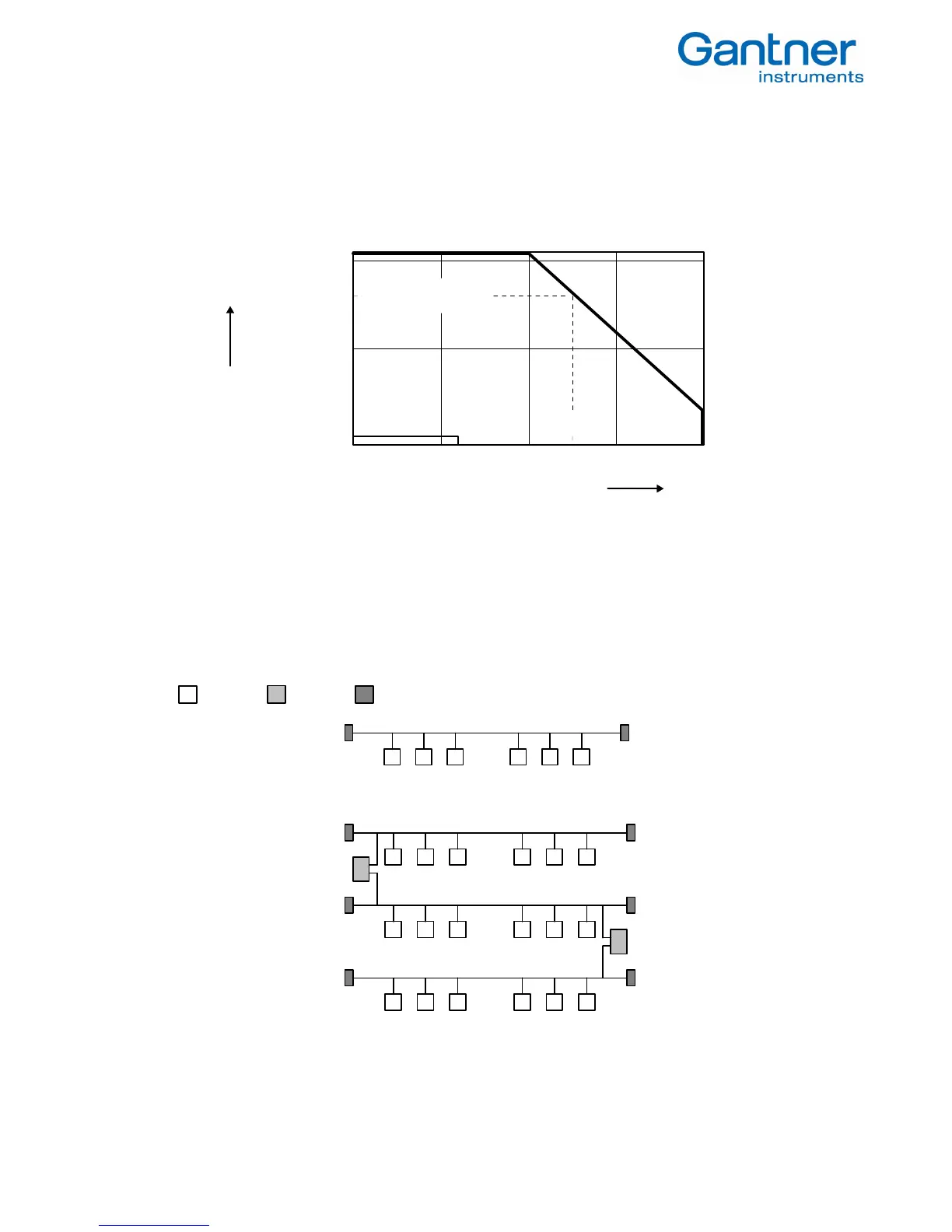
4.1. Bus interface
The bus interface in the sensor modules is an RS485 interface. Its advantages over traditional RS232 connections are a
larger number of users, its greater transmission speed, its greater immunity to interfering and the long line length that
are mostly required.
transmission speed
1 K 10 K 100 K
187,5 K
1 M 10 M
[bps]
10 m (32.5 ft)
100 m (325 ft)
1000 m (3.250 ft)
1200 m (3.900 ft)
transmission
600 m (1.950 ft)
RS 232
RS 422
RS 485
line length
Figure 4.1 Interrelation between transmission speed and line length
4.2. Bus Structure
The bus structure is a line structure where each bus segment will be blanked off with characteristic impedance on both
ends. Branches can be build up over a bi-directional signal amplifier, so called repeater. Other than that branches are
not permitted (no tree topology). The max. stub to a user is not allowed to exceed 30 cm (12 inches).
The following figures show a few examples for a possible set-up of bus topologies. The meaning of the symbols is:
: bus user : repeater : bus termination.
.....
Figure 4.2 Simple line structure
.....
.....
.....
Figure 4.3 Extended line structure