Q.series
Gantner Instruments GmbH
79
4 Connecting the modules → Q.bloxx A116: Connecting sensors
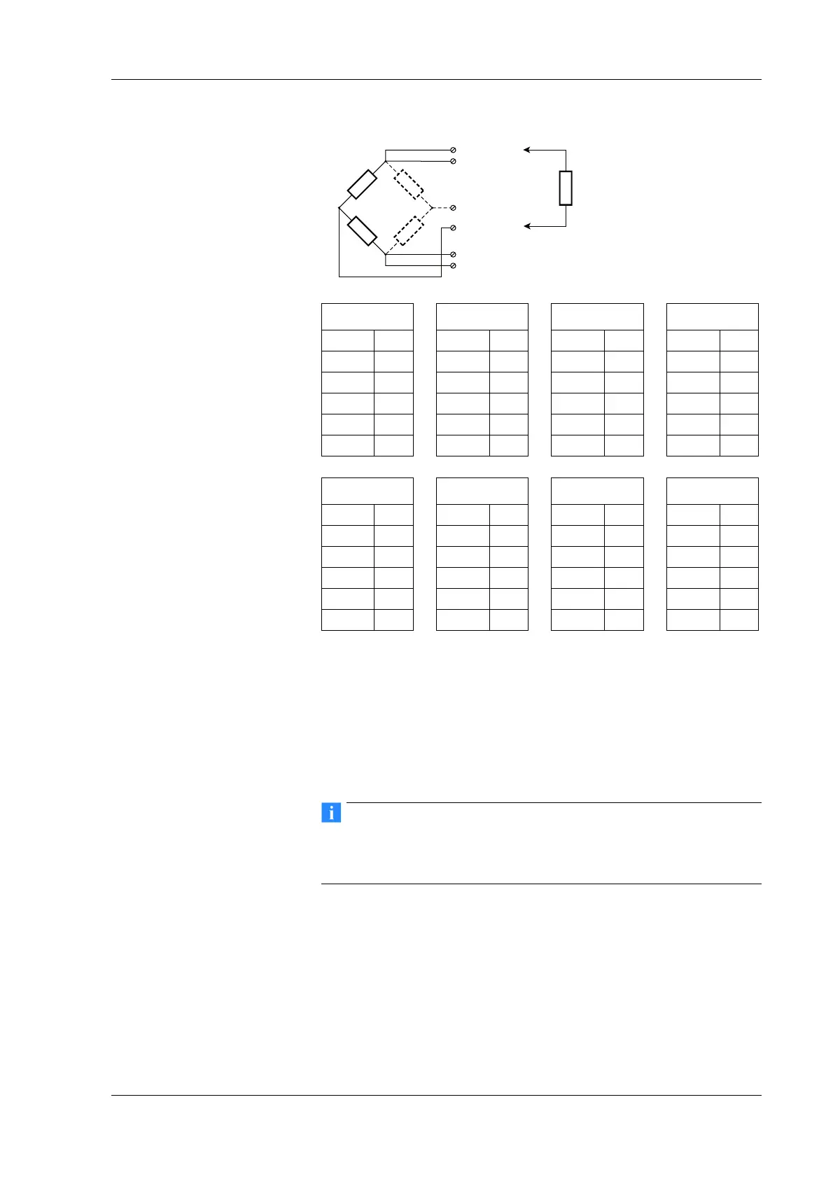
Fig. 4-73 A116, measurement with full and half bridges, direct con-
nection; U
SIG
= signal voltage (output signal), U
SEN
=
sense lead, U
EXC
= excitation voltage
You will find the terminal assignment for the terminal CT A116 or
the Cable A116 in the first section of this chapter. For the activa-
tion of the shunt resistance refer to Se
ction 4.18.3.
Information about the types of circuit and the respective advan-
tages and disadvantages can be found in Section 6.3, Connecting
sensors with sensing leads, page 143.
4.18.2 Strain-gauge quarter bridge
With this module, for the connection of strain-gauge quarter
bridges you do not need any special connection plugs as the 120
and 350 completion resistances are present in the module and
onl
y need to be activated. In addition you can activate the inter-
nal shunt resistance for test purposes.
Internal
shunt
100 k
U
Sig+
U
Sig–
U
Exc+
U
Sen+
U
Exc–
U
Sen–
Input 1
U
Exc+
A3
U
Exc–
A4
U
Sen+
B4
U
Sen–
A5
U
Sig+
B3
U
Sig–
B5
Input 2
U
Exc+
A7
U
Exc–
A8
U
Sen+
B8
U
Sen–
A9
U
Sig+
B8
U
Sig–
B9
Input 3
U
Exc+
A11
U
Exc–
A12
U
Sen+
B12
U
Sen–
A13
U
Sig+
B11
U
Sig–
B13
Input 4
U
Exc+
A15
U
Exc–
A16
U
Sen+
B16
U
Sen–
A17
U
Sig+
B15
U
Sig–
B17
Input 5
U
Exc+
A19
U
Exc–
A20
U
Sen+
B20
U
Sen–
A21
U
Sig+
B19
U
Sig–
B21
Input 6
U
Exc+
A23
U
Exc–
A24
U
Sen+
B24
U
Sen–
A25
U
Sig+
B23
U
Sig–
B25
Input 7
U
Exc+
A27
U
Exc–
A28
U
Sen+
B28
U
Sen–
A29
U
Sig+
B27
U
Sig–
B29
Input 8
U
Exc+
A31
U
Exc–
A32
U
Sen+
B32
U
Sen–
A33
U
Sig+
B31
U
Sig–
B33
 Loading...