10
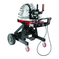
Figure 6
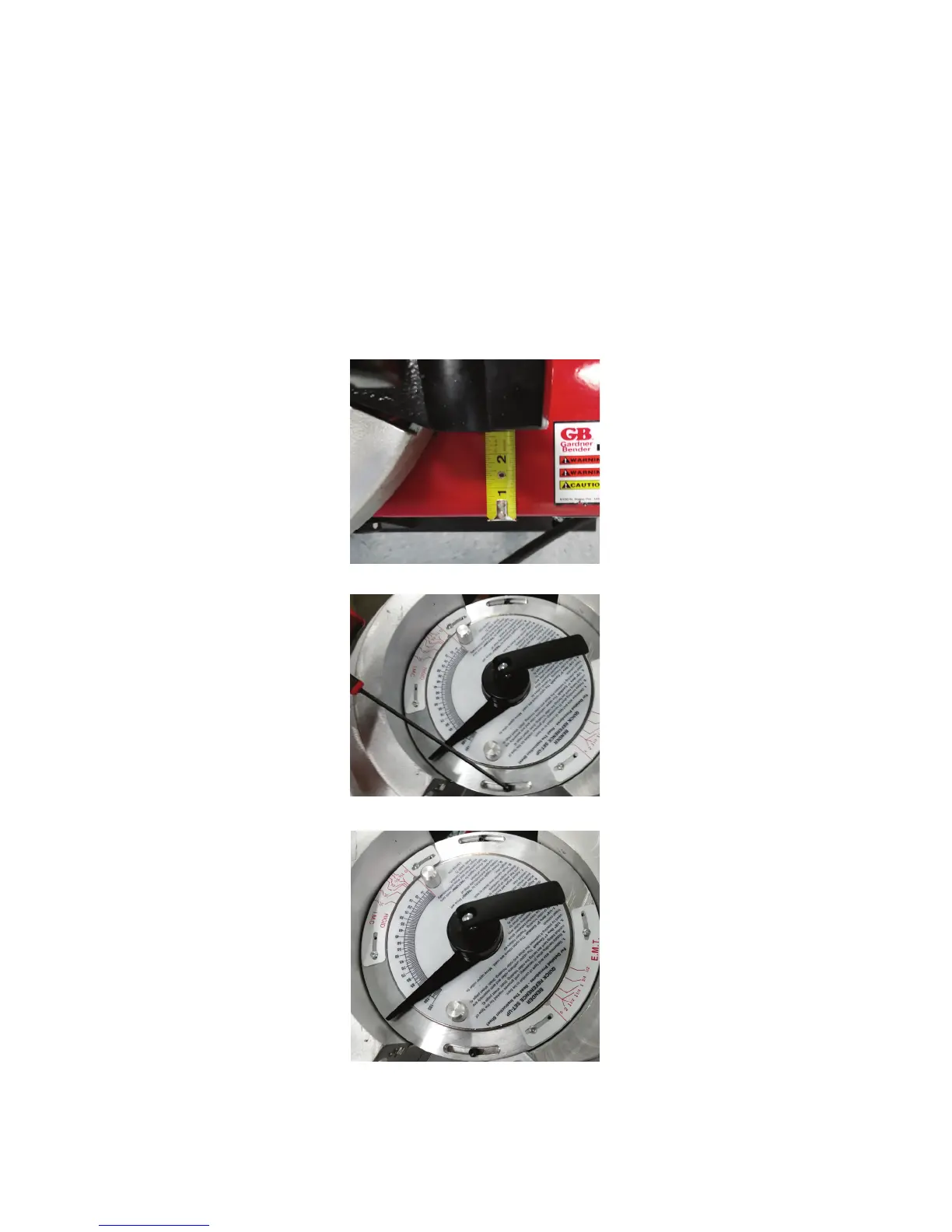
Figure 4
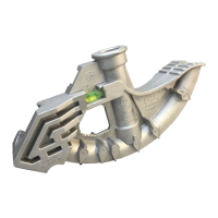
Figure 5
5.0 ZERO SET ADJUSTMENT
TO ENSURE ACCURATE BENDS, THE BENDER ZERO ADJUSTMENT MUST BE ACCOMPLISHED
AFTER RE-ASSEMBLY.
1. Plugs bend power cord into 110/115V outlet. Push upper roller assembly against the stop on the sprocket housing
(Figure 19).
2. Press and hold “ADVANCE” on pendant switch until RIGID side of shoe is facing the upper roller housing.
3. Place a straight edge against the shoe (clamp surface) and toward the upper roller shaft.
4. Jog the bender until 2 ½ inches exists between the straight edge and the shoe clamp (See Figure 4).
5. Loosen the trip ring mounting screws (See Figure 5). Rotate the trip ring until the zero light, on the pendant, is on
(Figure 6). Tighten the mounting screws and cover screws and cover screw slot with a clear silicone sealant.