18
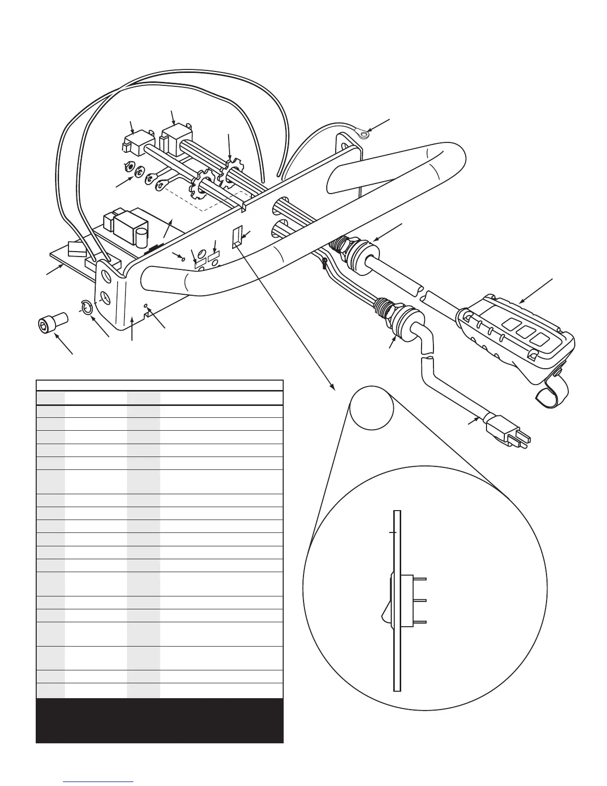
Figure 7
Handle and Control Circuit Assembly – HC12
15
5
2
6
13
9
10
12
15
6
14
16
11
3, 4
7, 8
1
18
17
19
Handle
Faceplate
White Wire
Note: Numbers molded
onto switch by the terminal
verify these before
attaching wires
Black Wire
to Circuit Board
Black Wire from
Power Plug
1
2
3
Wiring Diagram
for BMK3 Switch
HC12 Contents
Item # Part # # Req’d Description
1 CJ458885 1 Locknut
2 CM178647SR 1 Plug Assembly
3 CM32006 1 Receptacle, Power Cord
4 CM25061 2 Pin, Cord Receptacle
5 PO5C 1 Pendant Station Assm
6 Common Repl. 3 #6 -32 X
3
⁄8" LG. Button Hd.
Part Cap Screw
7 DA6152006 1 Receptacle, Pendant
8 CM27061 8 Pin, Receptacle
9 LK15 1 Decal, Kit
10 LK15 1 Decal, Kit
11 EC2006 1 Circuit Board
12 H905 1 Handle Assembly
13 Common Repl. 4
1
⁄2" - 13 x
7
⁄8" Alloy Plain Finish
Part Socket Head Cap Screw
14 DA7046900 1 Wire, Jumper
15 F1550 1 Grip, Cord
16 Common Repl. 1 #10 Hi-Collar Helical Spring
Part Lock Washer
17 Common Repl. 4
1
⁄2" Plain Finish High Collar
Part Lock Washer
18 CB25 1 Switch
19 RA19 1 Braking Resistor
Item 3 is packed with item 4 loose.
Item 7 is packed with item 8 loose.
Instructions provided for assembling loose connectors.
DA 7070900 Limit Switch Jumper (not shown) (for older units)