Do you have a question about the Gardner Denver EAH99C and is the answer not in the manual?
Explains how the compressor achieves air compression using helical rotors.
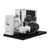
Details the path of air and oil through the compressor system.
Describes the oil system's role in lubrication, cooling, and sealing.
Explains the function of the turn valve for capacity control.
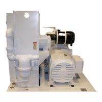
Provides instructions and safety precautions for lifting the compressor unit.
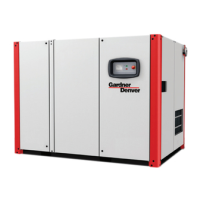
Specifies ideal conditions and placement for compressor installation.
Offers guidelines for installing and operating the unit in cold environments.
Details the connection and requirements for the discharge service line.
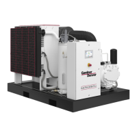
Explains water piping connections for water-cooled heat exchanger models.
Covers factory wiring and connection requirements for standard units.
Emphasizes electrical grounding requirements for safety and proper operation.
Outlines essential checks before initial unit startup.
Specifies the interval and importance of oil filter replacement.
Details the procedure for checking and ensuring correct motor rotation.
Guides on setting system pressure and avoiding over-pressure.
Provides procedures for starting the unit in both cold and hot conditions.
Describes the correct method for shutting down the compressor unit.
Explains the operation modes and keypad interface of the AutoSentry controller.
Details the functions and features of the microprocessor-based AutoSentry controller.
Covers the function, testing, and maintenance of pressure relief valves.
Describes the function of the blowdown valve for pressure relief.
Explains the inlet valve's role in controlling delivery and unloading.
Details solenoid valves for control and the pressure regulator for stable air supply.
Explains the turn valve, actuator, and associated solenoid valves for capacity control.
Covers transducers for pressure and switches for filter status.
Details fan and main starters for motor control and overload protection.
Outlines the function of the oil system in cooling, lubricating, and sealing.
Specifies the factory-recommended AEON lubricants for optimal performance.
Details the AEON 9000 SP synthetic lubricant and its benefits.
Discusses operation at sustained high discharge temperatures and lubricant life.
Explains the causes and effects of moisture accumulation in the oil system.
Describes how to read the oil level gauge and add/drain oil.
Provides recommended oil change intervals based on discharge temperature.
Details procedures for draining and cleaning the entire oil system.
Step-by-step guide for correctly filling the oil reservoir.
Explains the function of the oil filter and how to replace the element.
Describes the valve that controls oil temperature for proper warm-up.
Explains the adjustable valve for regulating water flow to the heat exchanger.
Details the oil separator's role in removing oil from the air stream.
Describes the standard heavy-duty, washable dry type air filter.
Guides on servicing the air filter element based on indicator light or hours.
Outlines conditions for replacing the air filter element.
Describes inspection and cleaning of the inlet tube during filter service.
Illustrates and describes the installation of coupling cushions.
Explains the direct connection via a flexible coupling and its lack of lubrication requirement.
Provides step-by-step instructions for assembling the coupling halves.
Notes that the coupling alignment is permanent via flanges.
Details the process for removing and replacing the coupling element.
Summarizes routine maintenance tasks and their frequency.
Daily checks including oil level, load/unload, pressure, and panel LEDs.
Checks for dirt accumulation on cooler cores and cooling fan.
Recommends changing the oil filter element.
Recommends changing the compressor lubricant.
Annual checks for relief valve and shutdown operation.
Lists common causes and remedies for starting failures.
Addresses issues causing short-time shutdowns, like temperature or fuses.
Details problems related to improper loading or unloading of the compressor.
Identifies causes for frequent cycling between loaded and unloaded states.
Explains slow starting issues related to Wye Delta settings or voltage.
Covers causes for reduced air output and pressure, like filter restrictions.
Lists reasons for high oil usage, such as carryover or leaks.
Discusses causes of high discharge temperature and their remedies.
Addresses issues causing oil to be carried over into the air lines.
Outlines general terms and conditions applicable to the warranty.
Specifies the duration of warranty coverage for different components.
Details the purchaser's responsibility for costs related to warranty claims.
States the exclusive warranty terms and limitations of liability.
| Brand | Gardner Denver |
|---|---|
| Model | EAH99C |
| Category | Air Compressor |
| Language | English |