13-9-663 Page 14
Both the air-cooled and water-cooled units require cooling air as well as air to the compressor inlet.
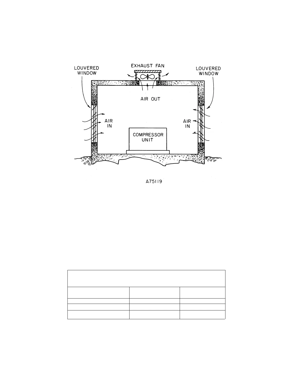
Proper ventilation MUST be provided; hot air must be exhausted from the compressor operating area. A
typical inlet-outlet air flow arrangement is shown in Figure 2-1.
Figure 2-1 – TYPICAL COMPRESSOR ROOM
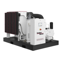
Air-Cooled Units - A combination oil/aftercooler is supplied as standard equipment on all air-cooled
units. The air-cooled unit with the standard enclosure requires sufficient flow, Figure 2-2, for the
compressor oil/aftercooling system and for electric motor cooling. Air is drawn into the unit at the motor
side of the enclosure and is exhausted at the oil cooler side. Do not block the air flow to and from the
unit. Allow three and one-half (3-1/2) feet (1.1 M) to the nearest obstruction on the starter end and control
box end of the unit. Allow three (3) feet (.9 M) to the nearest obstruction above and on other sides of unit.
For continuous efficiency, oil cooler cores must be periodically cleaned with either vacuum or compressed
air. If wet cleaning is required, shield motor and spray on a mild soap solution and flush with clean water.
Minimum Air Flow * For Compression and Cooling – Cubic Feet/Minute
(Cubic Meters/Minute)
HP (kW) Air Cooled Water Cooled
40 & 50 HP 6,500 1.400
60-100 HP (45-75 kW) 12,500 (354) 1,700 (48)
* 80° F (27° C) Inlet Air
Figure 2-2 – AIR FLOW CHART