13-18-609 Page 65
8-2
· A smaller gap will produce abnormal wear of the element by friction and excessive thermal
expansion – the latter could cause compressor damage by axially displacing the input shaft.
Make sure that keys are in proper alignment with key-ways on hubs.
· Apply a thread-locking compound to the hub set screws (M10 size) and tighten to 12.6 lb-ft (17
N-m) of torque. Reinstall coupling guard with provided fasteners.
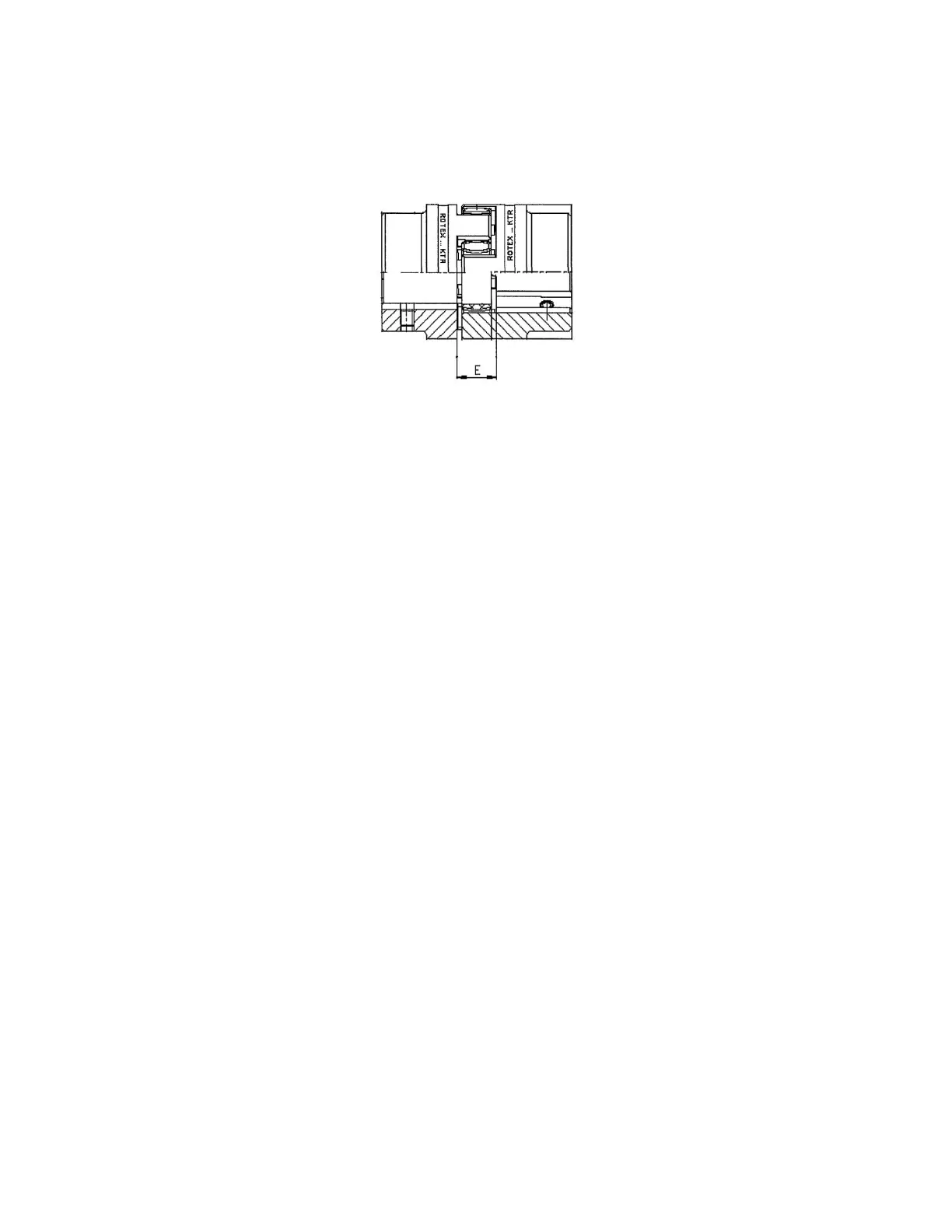
Figure 8- 2 – COUPLING ELEMENT
4. For hub-to-shaft interference fit hubs, main drive motor removal is necessary:
· Remove coupling guard by removing fasteners
· Remove coupling ventilation shroud by removing fasteners
· Drain oil entrained in discharge manifold by placing appropriate collection pan underneath elbow
segment and removing the 1/4” npt plug threaded tangent to said elbow. Proceed then to drop the
flanged of the discharge manifold by removing the bolts from compressor flange.
· Remove the following various lines connecting the package to the compressor. Make sure to
identify each line and matching [compressor-side connection] for proper reassembly – you may
also refer to the Parts List 13-18-505 for more details:
· Oil Injection hoses (one (1) base flow, two (2) solenoid valve flow)
· Bearing oil lubrication tube
· Drain nylon tube
· Inlet poppet valve pneumatic signal hose
· Air filter discharge hose
· Engage jack screws [built into base frame] until they make solid contact with the [front side] motor
mounting pads.
· Remove vertical support wall by removing fasteners and slide side-ways through door opening.
· Remove four bolts securing (main motor) rear support to base frame.
· Engage jack screw [built into base frame] until it makes solid contact with the compressor/motor
adaptor housing.
· Remove eight (8) bolts/nut/washer combos securing motor to adaptor housing.
· Lift/Pull away compressor and main motor adaptor from motor until coupling hubs separate and
allow removal of spider.
· Inspect coupling element for signs of wear and tear such as indentations, cracks, deformation,
extrusions, etc. It is highly recommended that the coupling element be replaced at this time.
· Re-assemble main motor and related components in reverse order.
· After engaging each hub on the matching recesses of the coupling element, check that the gap
between the hub flats (see dimension “E” on Figure 8-2) is within 1.38/1.50 in (35/38 mm). A
smaller gap will produce abnormal wear of the element by friction and excessive thermal expansion
– the latter could cause compressor damage by axially displacing the input shaft. Make sure that
keys are in proper alignment with key-ways on hubs.
· Apply a thread-locking compound to the hub setscrews (M10 size) and tighten to 12.6 lb-ft (17 N-
m) of torque. Reinstall coupling guard and coupling ventilation shroud with provided fasteners.




 To Next Page