Installation Procedures
GNS 480 (CNX80) Installation Manual 560-0982-01 Rev L 2-5
2.5.2.3 Multiple Baro Correction Sources
The GNS 480 can accept barometric correction from an altimeter with a baro correction potentiometer
output, ARINC 429 ADC, FADC, MX20/GMX 200 display, or another GNS 480.
If multiple sources of barometric correction data are supplied to the GNS 480, only valid data from the
highest priority source is used. If the highest priority source becomes unavailable, data is taken from the
next-highest priority source. The priorities of the barometric correction sources are as follows (from
highest to lowest):
1. Baro correction potentiometer (from altimeter)
2. FADC (use of the baro correction and baro-corrected altitude can be disabled as part of the setup)
3. ADC (correction derived from ARINC 429 labels 203 and 204)
4. MX20/GMX 200 Display
5. Manual entry into GNS 480 (allowed only if no other baro correction sources are available)
NOTE
Baro correction data received from a second GNS 480 will also be derived from one of the
above sources. Data received on the GNS 480 cross-talk input is treated as if it is received
directly from the source that is supplying baro correction to the second GNS 480. If the
direct input and the GNS 480 cross-talk input have the same priority, data from the direct
input is used.
2.5.3 Mounting Considerations
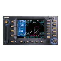
The GNS 480 is designed to mount in the avionics stack in the aircraft instrument panel within view and
reach of the pilot. The preferred location would minimize pilot head movement when transitioning
between looking outside of the cockpit and viewing / operating the GNS 480. The location should be such
that the GNS 480 is not blocked by the glare shield on top, or by the throttles, control yoke, etc. on the
bottom.
For VFR-only installations, the GNS 480 must be mounted in the aircraft manufacturer approved location
or other FAA approved location.
For IFR GPS installations, the GNS 480 must be mounted within the acceptable field-of-view, as defined
in 2.5.3.1. If the GNS 480 cannot be mounted within the acceptable field-of-view this does not preclude
IFR GPS operation, but additional FAA approval may be required.
To preclude the requirement for an external CDI/HSI source selection annunciation in IFR installations,
the GNS 480 must be located in close proximity to the main (switched) CDI/HSI, as defined in 2.5.3.2. If
the GNS 480 cannot be within the required distance of the CDI/HSI, then a CDI/HSI source selection
annunciator must be provided (a CDI/HSI with a built-in annunciation may also be used in lieu of a
separate external annunciator to satisfy the annunciation requirement).
For installations where two GNS 480’s are installed, the second GNS 480 may be installed in the radio
stack below the primary unit, or in a radio stack to the right of the primary radio stack (a second stack). In
these instances, the primary GNS 480 must be installed within the acceptable field-of-view, and the
preferred location for the secondary GNS 480 is also within the acceptable field of view. However, the
secondary GNS 480 may be installed outside of the acceptable field-of-view but can only be used as a
backup in the event of a failure of the primary GNS 480.

 Loading...