10 -
System Overview.
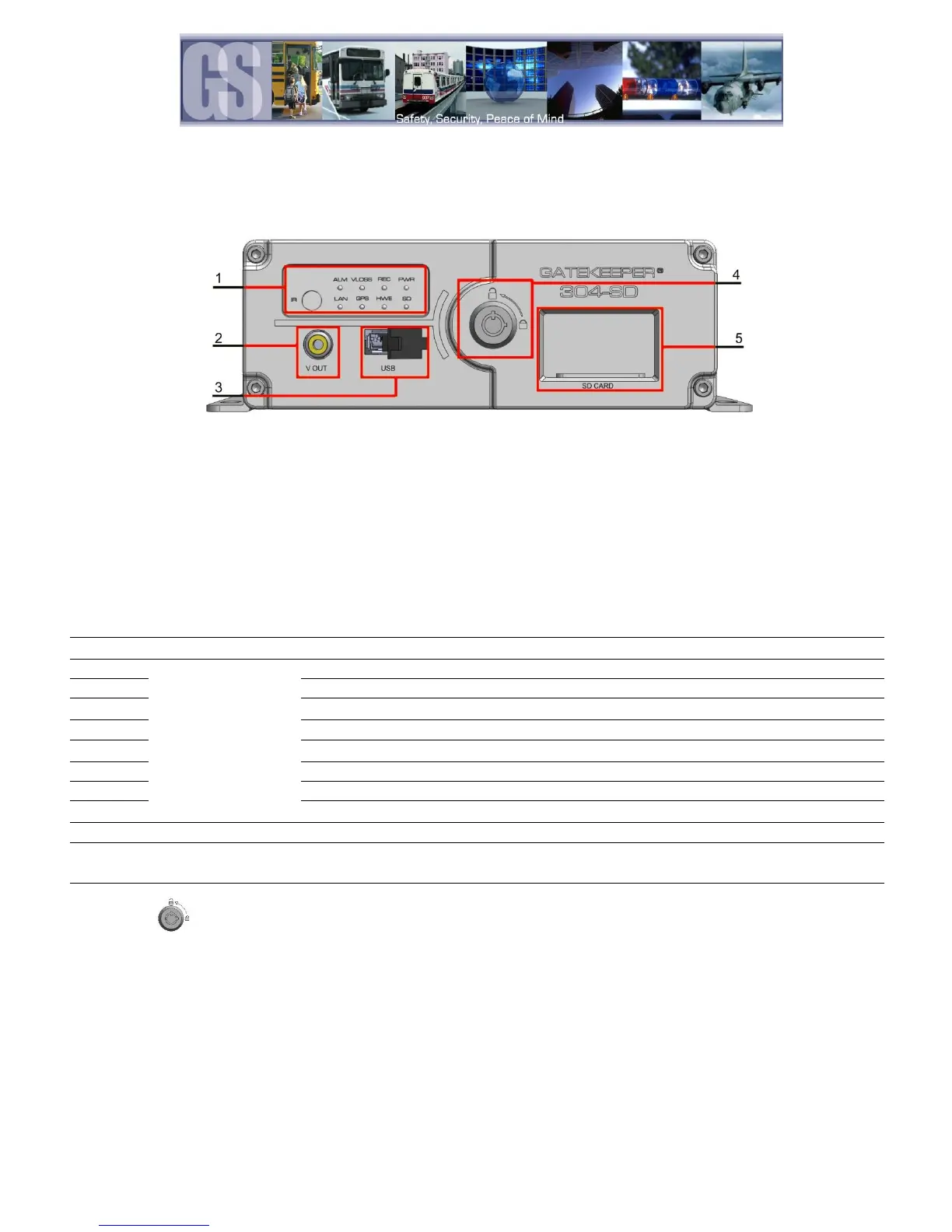
Front View
1. LED Status Indicators. (See Table 1)
2. V OUT. Connects to External Display
3. USB. Used for Saving/Uploading configurations and
updating the system firmware.
4. Lock. Allows access to the SD Card Slot (5) and can
start & stop recording of video.
5. SD Card. Houses the SD Card used for recording Video.
Video output to an external display, e.g. TV / Portable DVD Player.
The various LED’s
are status
indicators.
Flashes to indicate 304SD is recording
Illuminated when GPS signal is present
Displays Network activity
Illuminated when power present
A Physical Hardware error, or, no SD Card.
Signifies the 304SD has received an Alarm input.
Flashes if Video Loss has occurred.
For receiving signals from the Remote Control.
Use to backup recorded video files; download/upload configurations and firmware
upgrade
The SD card slot needs to be locked before booting up the system, otherwise, the boot
sequence will be unsuccessful. The 304SD will be in standby mode anytime the SD slot
is unlocked.
Table 1: LED Status Indicators.