14 -
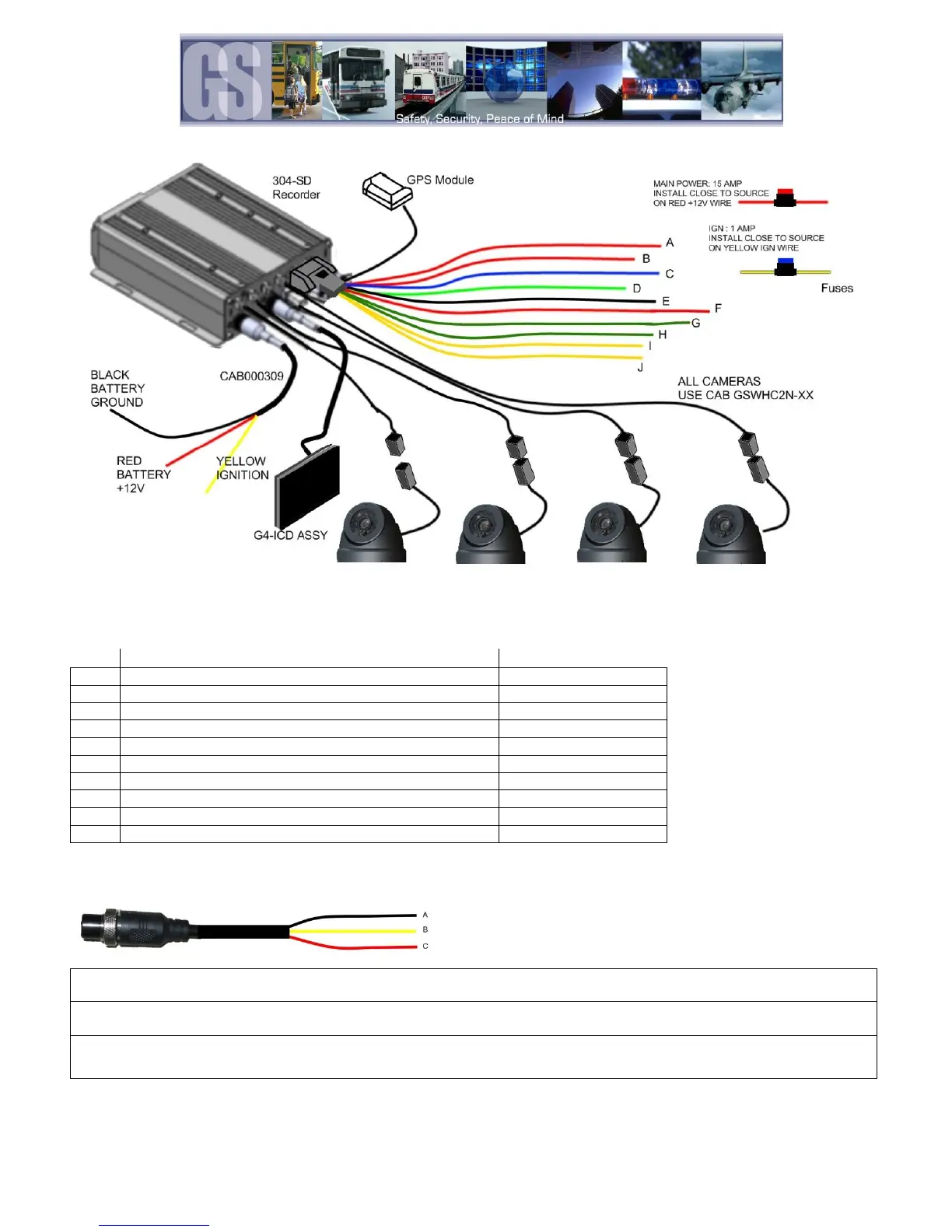
Figure 4: 304-SD Wiring, Including Optional Accessories.
SENSORS IN : 1- 6 (see for configuration)
SENSORS IN : 7 – 8 (Currently not used)
SPEED + / - (not supported)
232-1 (COM connection, Not Supported)
232-2 (COM connection, Not Supported)
485-3 (Connect to the Driver Alert Button)
485-4 (Connect to the G, Inertia, Sensor)
Table 2: CAB000323 Definitions.
Power Connector (CAB000309)
GND (A) Input (Black): Connect to the negative terminal of the battery, -12V.
Ignition (B) (Yellow): Connect to vehicle ignition. +12V signal required to activate the 304SD. Ensure that the provided 1
AMP In-Line fuse is used
Positive (C) (Red): Connect to the positive terminal of the battery, +12V. Ensure that the provided 15AMP In-Line fuse is
used
Figure 5: Power Connections.